Lithium ion secondary battery

a secondary battery and lithium ion technology, applied in the direction of cell components, final product manufacturing, sustainable manufacturing/processing, etc., can solve the problems of short-circuit failure, limitation of elongation percentage, and inability to improve the maximum lithium ion conductivity, etc., to achieve safety and high-rate characteristics, good discharge characteristics, and good heat resistance.

Active Publication Date: 2007-08-23
PANASONIC CORP
View PDF13 Cites 15 Cited by
  • Summary
  • Abstract
  • Description
  • Claims
  • Application Information

AI Technical Summary

Benefits of technology

[0014] One object of the present invention is to provide a lithium ion secondary battery which can achieve both safety and high-rate characteristics, with a usage of a porous film which can secure heat resistance, necessary strength, and lithium ion conductivity by limiting a resin binder content in the porous film to a small amount, while selecting a constituent monomer of the resin binder.
[0047] According to an embodiment of the present invention, sufficient micropores for lithium ion to move to the electrode surface side can be secured while securing flexibility of the porous film, since the amount of the resin binder in the porous film is smaller in the first surface side in contact with the surface of the electrode, and larger in the second surface side opposite to the first surface side. Additionally, since the porous film has flexibility, separation of the porous film in manufacturing processes is suppressed to prevent an internal short circuit. Therefore, a lithium ion secondary battery with higher quality and safety can be provided.

Problems solved by technology

However, even though many micropores are formed in the porous film, when the size of the micropores is inappropriate for the lithium ion transfer, lithium ion conductivity can not be improved to the maximum.
Since tensile stress is applied on the electrode plate on which a porous film is formed at the time of forming the electrode plate group, the porous film might crack and cause a short-circuit failure.
However, in order to secure lithium ion conductivity of the porous film, the resin binder content has to be limited to a small amount, so the attention is not given to the limitation of the elongating percentage.

Method used


Image

  • Lithium ion secondary battery
  • Lithium ion secondary battery
  • Lithium ion secondary battery

Examples


example 1

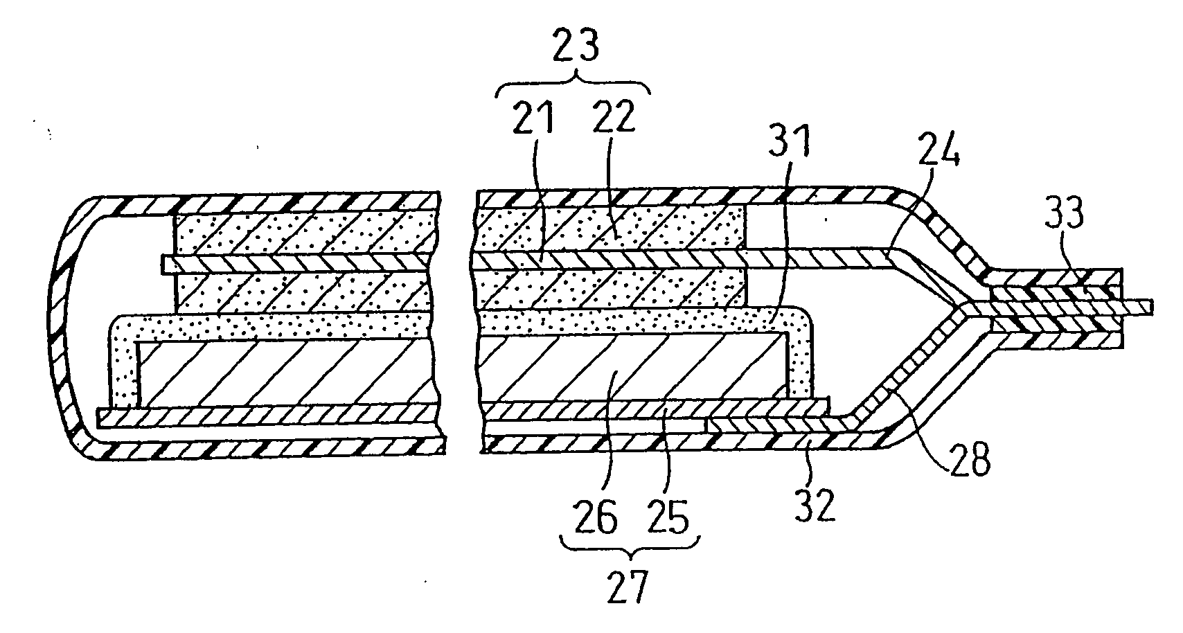
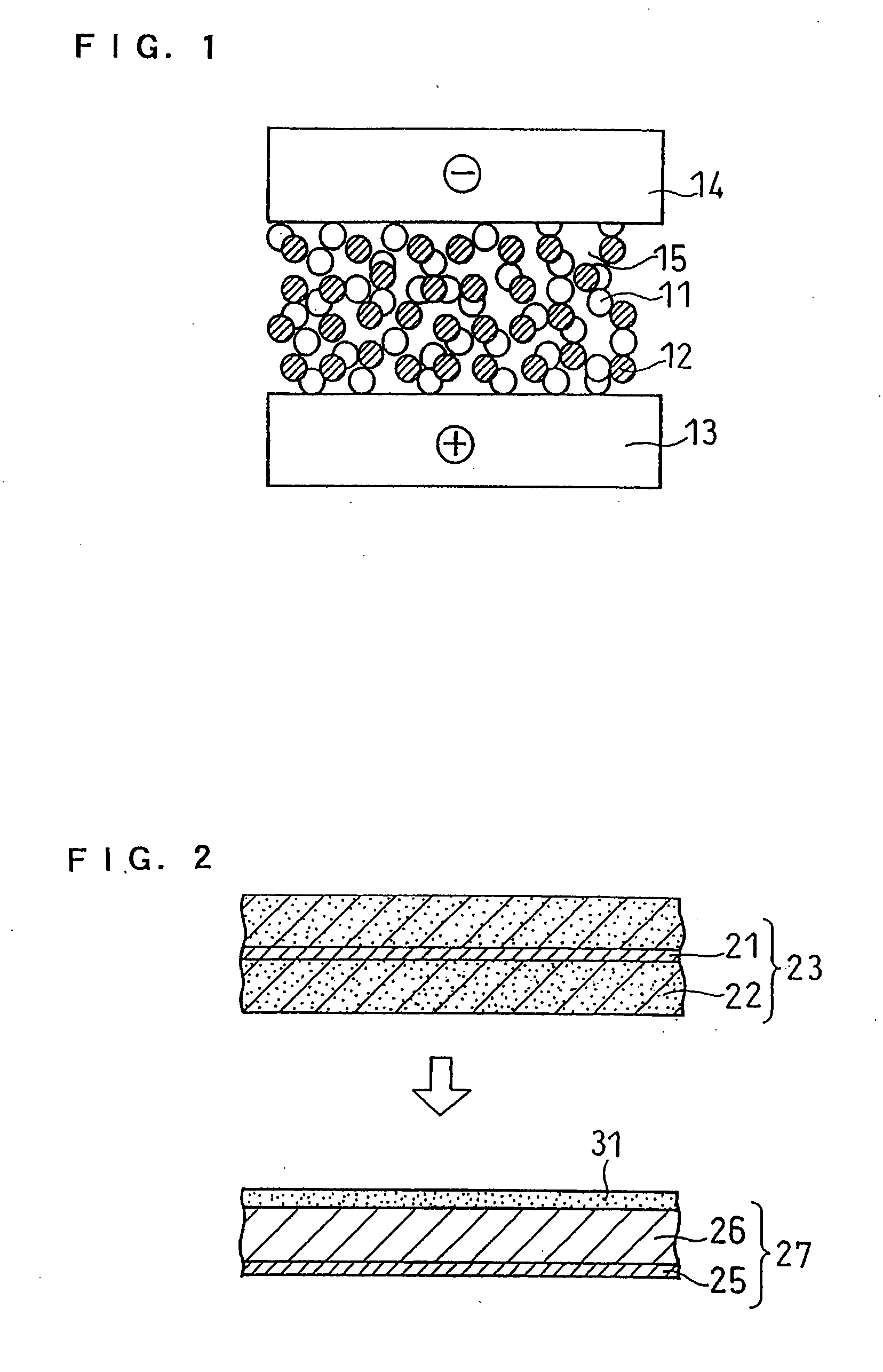
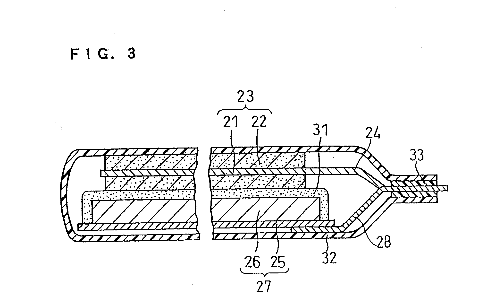
[0119]FIG. 2 and FIG. 3 are referred in the explanation.

(i) Fabrication of Positive Electrode

[0120] To 100 parts by weight of LiCoO2, 4 parts by weight of polyvinylidene fluoride (PVDF) as a binder and 3 parts by weight of acetylene black as a conductive agent were added and subsequently an appropriate amount of NMP (N-methyl-2-pyrrolidone) was added and then kneaded, to prepare a positive electrode material mixture paste.

[0121] The obtained positive electrode material mixture paste was applied on both sides of an aluminum foil core material 21 with a thickness of 20 μm, and then rolled so that the density of the active material (density of LiCoO2) in the positive electrode material mixture 22 became 3.3 g / ml, to produce a positive electrode 23. A positive electrode lead 24 made of aluminum was connected to the positive electrode 23.

(ii) Fabrication of Negative Electrode

[0122] To 100 parts by weight of spherical artificial graphite, 1 part by weight of styrene-methacrylic aci...

example 2

(i) Fabrication of Positive Electrode and Negative Electrode

[0148] A positive electrode and a negative electrode were fabricated in the same manner as Example 1.

(ii) Formation of Porous Film

[0149] A raw material paste of porous film was prepared in the same manner as Example 1. Herein, each raw material paste of porous film was prepared by dispersing a filler and a resin binder in NMP with the ratio shown in Table 3 and kneading them. The raw material content in the paste (a total of the filler and the resin binder) was set as 50 wt % in any of the cases. For the filler, an alumina (Al2O3) with an average particle size of 0.4 μm was used alone.

TABLE 3Amount of resinbinder per 100AverageAverage poreparts by weightparticlesize ofof fillersizemicropore inPeeling ofHigh rate(parts by weight)of fillerporous filmporouscharacteristicExampleBM500BPVDF(μm)(μm)film(%)A20.750.750.40.05NONE87.6Com. 1b0.50.50.40.05EXIST—B2330.40.05NONE84.1C2440.40.05NONE80.9Com. 2b550.40.05NONE76.5Com. 3b...

example 3

(i) Fabrication of Positive Electrode

[0165] A positive electrode was fabricated in the same manner as Example 1 except that the size of the electrode plate was changed to a predetermined size.

(ii) Fabrication of Negative Electrode

[0166] A negative electrode was made in the same manner as Example 1 except that the negative electrode material mixture was carried on both surfaces of the copper foil core material to give a density of 1.4 g / ml of the active material (density of graphite), and that the size of the electrode plate was changed to a predetermined size.

(iii) Formation of Porous Film

[0167] A filler and a resin binder were dispersed in NMP in proportions shown in Table 4, and then kneaded, to prepare a raw material paste of porous film. The raw material content in the paste (the total of the filler and the resin binder) was set as 50 wt % in any of the cases.

[0168] As in Example 1, for the filler, the “alumina a” with an average particle size of 0.4 μm was used alone, ...


PUM

PropertyMeasurementUnit
pore sizeaaaaaaaaaa
temperatureaaaaaaaaaa

Abstract

A lithium ion secondary battery includes a positive electrode capable of absorbing and desorbing lithium ion, a negative electrode capable of absorbing and desorbing lithium ion, a porous film interposed between the positive electrode and the negative electrode, and a non-aqueous electrolyte: the porous film being adhered to a surface of at least one of the positive electrode and the negative electrode; the porous film including a filler and a resin binder; the resin binder content in the porous film being 1.5 to 8 parts by weight per 100 parts by weight of the filler; and the resin binder including an acrylonitrile unit, an acrylate unit, or a methacrylate unit.

Description

TECHNICAL FIELD [0001] The present invention relates to a lithium ion secondary battery having a porous film including a filler and a resin binder, and adhered to a surface of at least one of a positive electrode and a negative electrode. The present invention relates to an excellently safe lithium ion secondary battery in which a thermal runaway will not occur even when an internal short circuit is caused. BACKGROUND ART [0002] As electronic devices become more and more portable and wireless, small and lightweight lithium ion secondary batteries with high energy density, are receiving attention as a power source for these devices. Lithium ion secondary batteries have a positive electrode comprising a lithium-containing transition metal oxide or the like, a negative electrode comprising a carbon material or the like, and a non-aqueous electrolyte. [0003] In lithium ion secondary batteries, a separator is interposed between the positive electrode and the negative electrode to electro...

Claims


Application Information

Patent Timeline
Patent Type & Authority Applications(United States)
IPC IPC(8): H01M2/16H01M4/13H01M4/131H01M4/133H01M10/0525H01M10/0587H01M10/36H01M50/403H01M50/414H01M50/469
CPCH01M2/145H01M2/1653H01M2/166H01M2/1673H01M2/18Y10T29/49115H01M4/131H01M4/133H01M10/0525H01M10/0587Y02E60/122H01M4/13Y02E60/10H01M50/403H01M50/446H01M50/46Y02P70/50H01M50/469H01M50/414H01M50/491H01M50/449H01M50/42H01M50/489H01M50/443H01M50/431
Inventor OHATA, TSUMORUNAKAJIMA, JUNJIHAYASHI, TETSUYATAKANO, TAKASHIIKUTA, SHIGEOSUZUKI, KOHEINISHIDA, KOUJIFUKUNAGA, MASAOFUJINO, AKIKO
Owner PANASONIC CORP
Why Eureka
Try Eureka