

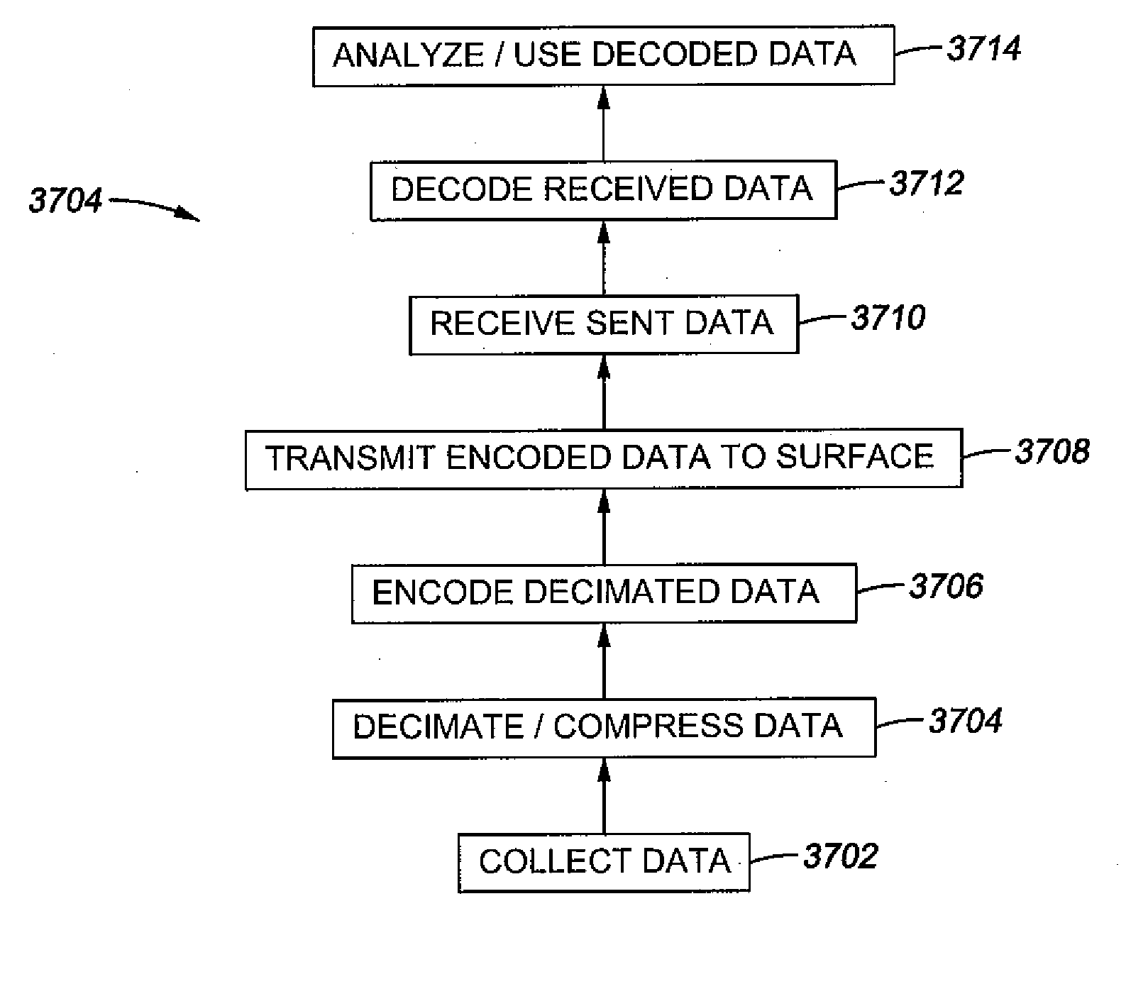
Systems and methods for well data compression
a data compression and data technology, applied in the field of well logging, can solve the problems of inability to communicate in real time with the tools, the current limitations of telemetry, and the length of the tes
- Summary
- Abstract
- Description
- Claims
- Application Information
AI Technical Summary
Problems solved by technology
Method used
Image

Examples
Embodiment Construction
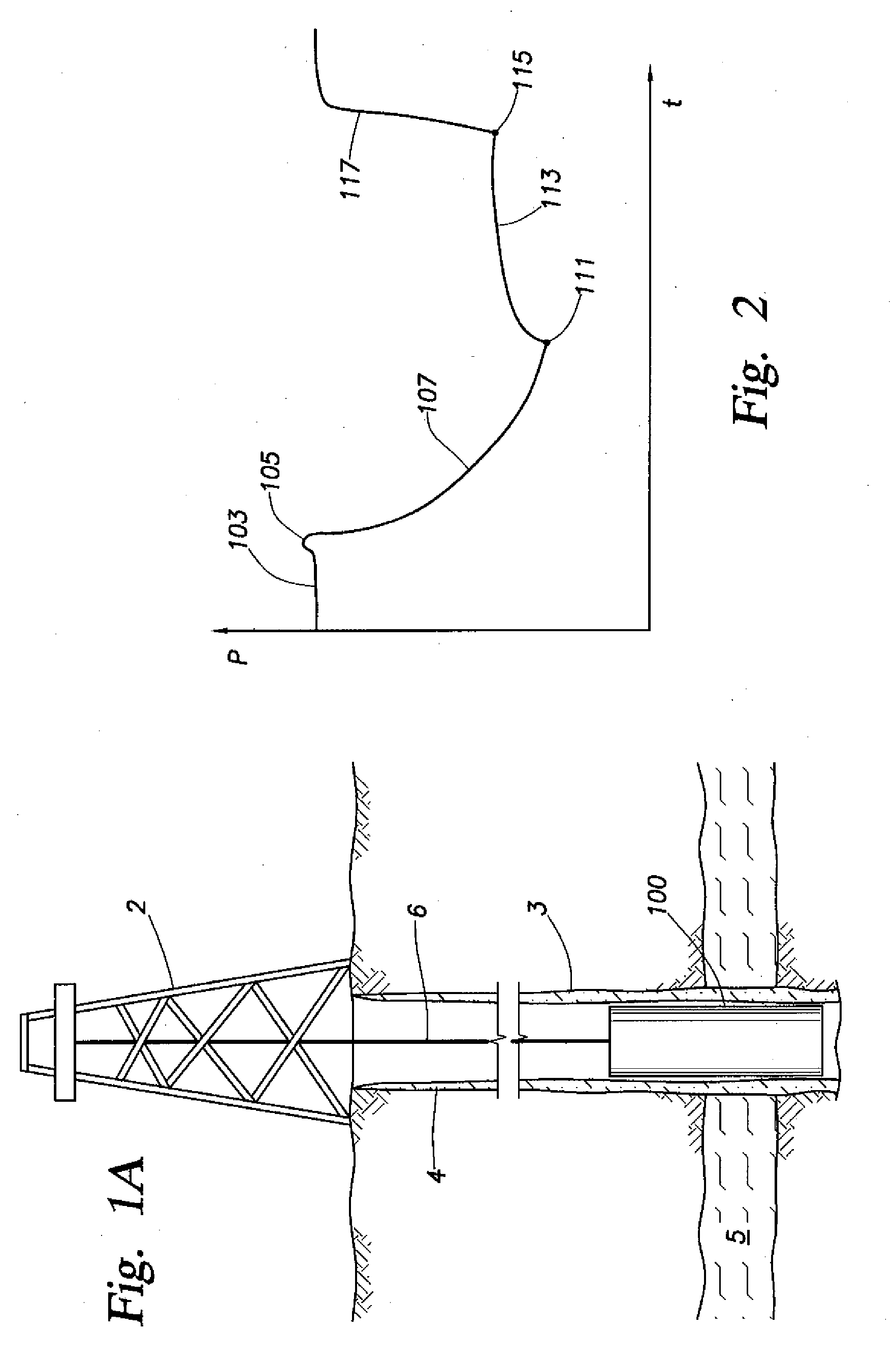
[0066] An embodiment for estimating formation properties (e.g. formation pressures and mobilities) is shown in the block diagram of FIG. 3. As shown in FIG. 3, the method includes an investigation phase 13 and a measurement phase 14.
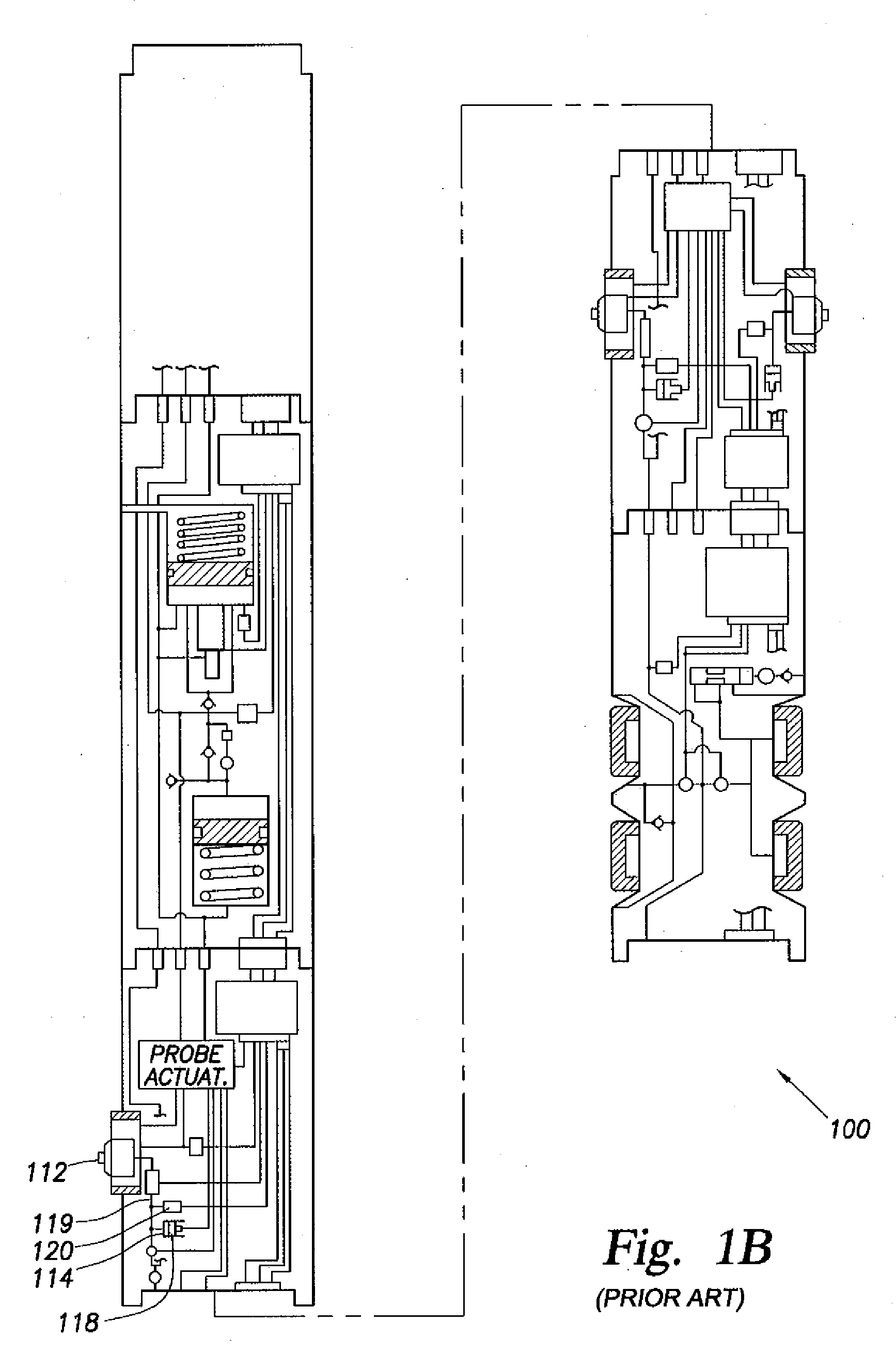
[0067] The method may be practiced with any formation tester known in the art, such as the tester described with respect to FIGS. 1A and 1B. Other formation testers may also be used and / or adapted for embodiments of the invention, such as the wireline formation tester of U.S. Pat. Nos. 4,860,581 and 4,936,139 issued to Zimmerman et al., the downhole drilling tool of U.S. Pat. No. 6,230,557 B1 issued to Ciglenec et al. and / or U.S. Patent Application No. 2005 / 0109538, the entire contents of which are hereby incorporated by reference.
[0068] A version of a probe module usable with such formation testers is depicted in FIG. 4. The module 101 includes a probe 112a, a packer 110a surrounding the probe, and a flow line 119a extending from the probe into the mo...
PUM
 Abstract
Description
Claims
Application Information