Optical computational system

a computational system and optical technology, applied in the field of spectroscopy analysis systems, can solve the problems of inability to accurately measure the data relating to one, inability to convert simple light intensity measurement to information, and inability to accurately estimate the accuracy of the estima

Inactive Publication Date: 2006-10-17
HALLIBURTON ENERGY SERVICES INC +1
View PDF39 Cites 150 Cited by
  • Summary
  • Abstract
  • Description
  • Claims
  • Application Information

AI Technical Summary

Benefits of technology

[0022]Accordingly, it is an object of the present invention to provide an improved system for deriving information from light.

Problems solved by technology

In general, a simple measurement of light intensity is difficult to convert to information because it likely contains interfering data.
It is often impossible to adequately measure the data relating to one of these factors since the contribution of the other factors is unknown.
Depending on the circumstances, however, the estimate may be unacceptably inaccurate since factors other than ethylene may affect the intensity of the wavelength bands.
Unfortunately, however, charge couple devices and their required operational instrumentation are very expensive.
A typical instrument including such sensitive detectors, and the spectrographs needed for their operation, generally cost around $250,000.
Furthermore, the devices are sensitive to environmental conditions.
The power requirements, cooling requirements, cost, complexity and maintenance requirements of these systems have made them impractical in many applications.

Method used


Image

  • Optical computational system
  • Optical computational system
  • Optical computational system

Examples


Embodiment Construction

[0071]Reference will now be made in detail to presently preferred embodiments of the invention, one or more examples of which are illustrated in the accompanying drawings. Each example is provided by way of explanation of the invention, not limitation of the invention. In fact, it will be apparent to those skilled in the art that modifications and variations can be made in the present invention without departing from the scope or spirit thereof. For instance, features illustrated or described as part of one embodiment may be used on another embodiment to yield a still further embodiment. Thus, it is intended that the present invention covers such modifications and variations as come within the scope of the invention.

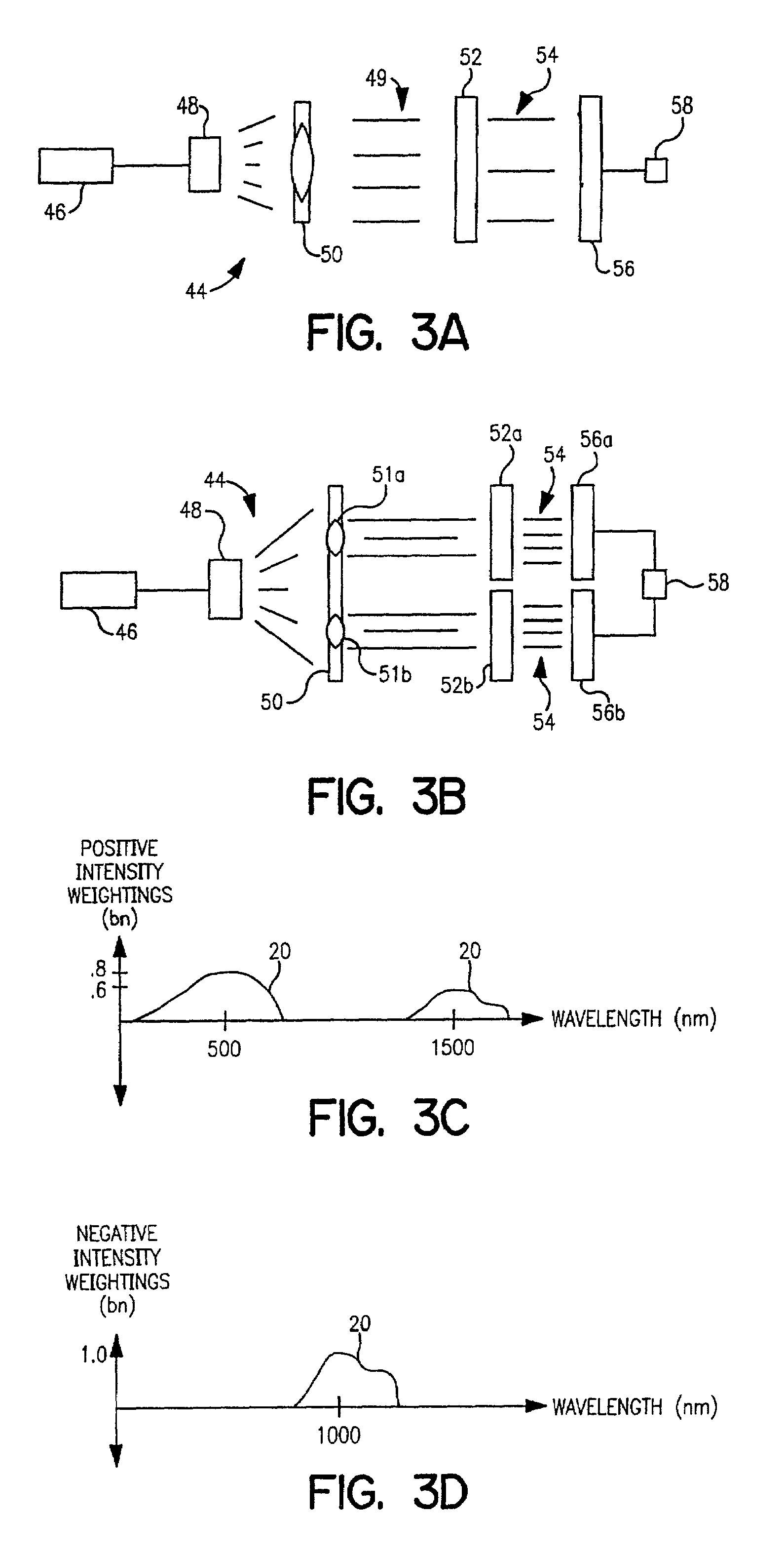
[0072]In one presently preferred embodiment of an optical analysis system, shown generally at 44 in FIG. 3A, an energy source 46 illuminates a sample substance 48. Light passing through or reflected from sample 48 is collimated by collimator 50, which includes one or mor...


PUM


Abstract

In optical filter systems and optical transmission systems, an optical filter compresses data into and/or derives data from a light signal. The filter way weight an incident light signal by wavelength over a predetermined wavelength range according to a predetermined function so that the filter performs the dot product of the light signal and the function.

Description

[0001]This is a continuation of application Ser. No. 09 / 286,879 filed Apr. 6, 1999, now abandoned the entire disclosure of which is incorporated by reference herein.BACKGROUND OF THE INVENTION[0002]The present invention relates to spectroscopy analysis systems. More particularly, the invention relates to improvements in the compression of data carried by light so that information about the light may be obtained.[0003]Light conveys information through data. When light interacts with matter, for example, it carries away information about the physical and chemical properties of the matter. A property of the light, for example its intensity, may be measured and interpreted to provide information about the matter with which it interacted. That is, the data carried by the light through its intensity may be measured to derive information about the matter. Similarly, in optical communications systems, light data is manipulated to convey information over an optical transmission medium, for e...

Claims


Application Information

Patent Timeline
Patent Type & Authority Patents(United States)
IPC IPC(8): H04B10/04H01S3/13G01J3/18G01J3/28G01J3/36G01J3/51
CPCG01J3/18G01J3/28G01J3/2803G01J3/36G01J3/502G01J3/51G01J3/524
Inventor MYRICK, MICHAEL L.
Owner HALLIBURTON ENERGY SERVICES INC
Why Eureka
Try Eureka