Control apparatus and method for internal combustion engine

a technology of control apparatus and internal combustion engine, which is applied in the direction of engine controllers, electric control, machines/engines, etc., can solve the problems of difficult control to minimize the overall catalyst degradation

Inactive Publication Date: 2007-08-30
TOYOTA JIDOSHA KK
View PDF2 Cites 18 Cited by
  • Summary
  • Abstract
  • Description
  • Claims
  • Application Information

AI Technical Summary

Benefits of technology

[0009]The invention provides a control apparatus and method for an internal combustion engine including two cylinder groups, upstream catalysts provided for the respective cylinder groups, a downstream catalyst provided in an exhaust passage downstream of th...

Problems solved by technology

That is, in an internal combustion engine having the above-described arrangement of exhaust components, it has been difficult t...

Method used


Image

  • Control apparatus and method for internal combustion engine
  • Control apparatus and method for internal combustion engine
  • Control apparatus and method for internal combustion engine

Examples


Embodiment Construction

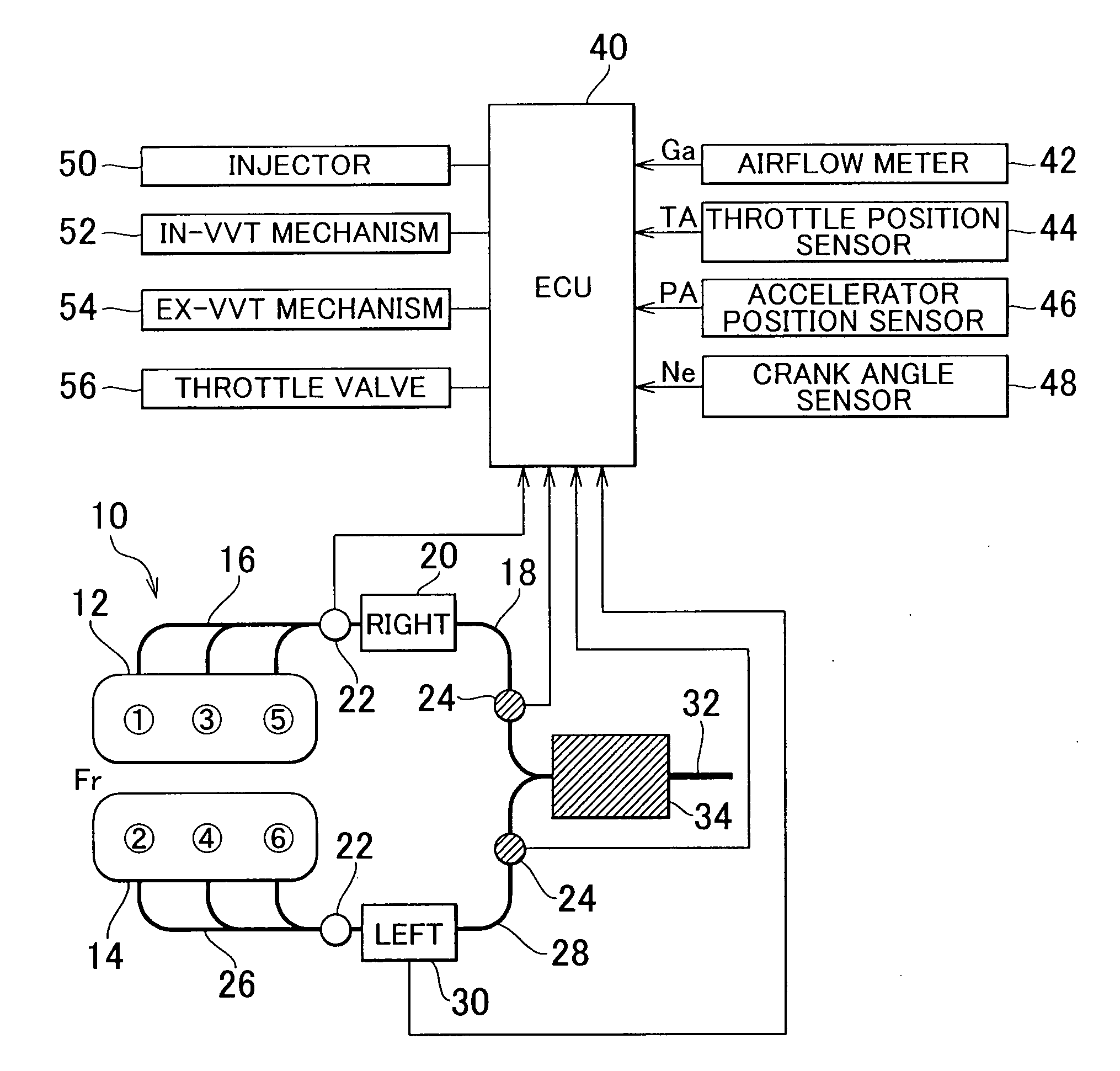
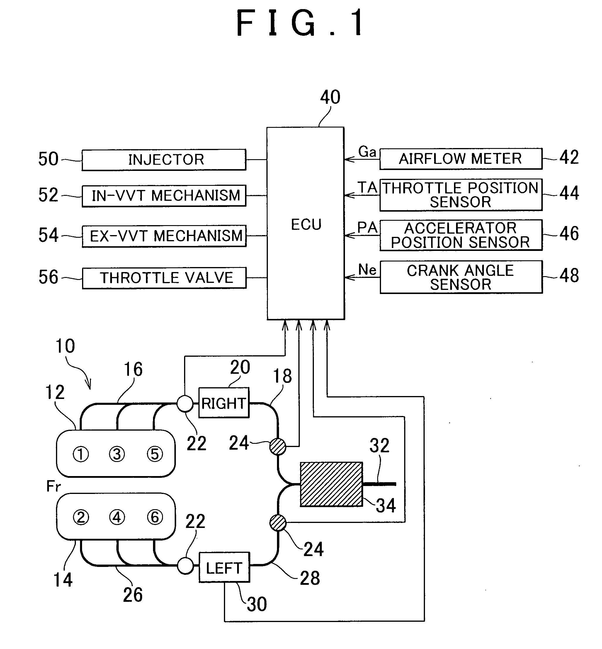
[0024]FIG. 1 illustrates the configuration of the system according to a first exemplary embodiment of the invention, which mainly shows the exhaust system of an internal combustion engine 10. Referring to FIG. 1, the system of the first exemplary embodiment includes the internal combustion engine 10 that is a V6 engine having a right bank 12 consisting of cylinders #1, #3, and #5 and a left bank 14 consisting of cylinders #2, #4, and #6.

[0025]The exhaust system of the internal combustion engine 10 includes a right exhaust manifold 16 connected to the right bank 12 and a right exhaust pipe 18 connected to the right exhaust manifold 16. The exhaust gases discharged from the three cylinders in the right bank 12 converge at the right exhaust manifold 16 and then flow therefrom to the right exhaust pipe 18. A right upstream catalyst 20 that purifies exhaust gas is provided midway in the right exhaust pipe 18, and an air-fuel ratio sensor 22 is provided upstream of the right upstream cata...


PUM


Abstract

A control apparatus for an internal combustion engine that includes right and left banks, first and second catalysts provided in the right and left exhaust pipes, respectively, and a downstream catalyst provided in a common exhaust pipe downstream of the upstream catalysts is adapted to alternately switch execution of catalyst degradation minimization and execution of fuel cut between the two banks if at least one of the temperature of the first catalyst and temperature of the second catalyst is higher than a predetermined value during deceleration of the internal combustion engine.

Description

INCORPORATION BY REFERENCE[0001]The disclosure of Japanese Patent Application No. 2006-048429 filed on Feb. 24, 2006 including the specification, drawings and abstract is incorporated herein by reference in its entirety.BACKGROUND OF THE INVENTION[0002]1. Field of the Invention[0003]The invention relates to a control apparatus and method for an internal combustion engine, and particularly to a control apparatus and method for an internal combustion engine that includes upstream catalysts provided for multiple cylinder groups, respectively, and a downstream catalyst that is provided in an exhaust passage downstream of the confluence of exhaust passages provided downstream of the upstream catalysts, respectively.[0004]2. Description of the Related Art[0005]For example, Japanese patent application publication No. JP-A-08-144814 describes a control apparatus that performs fuel cut when the internal combustion engine is decelerating. According to this control apparatus, execution of the ...

Claims


Application Information

Patent Timeline
IPC IPC(8): F01N3/00F01N3/10
CPCF02D41/0082F02D41/0087F02D41/0235F01N13/011F02D2200/0804F01N13/009F02D41/123
Inventor HOSHI, KOICHI
Owner TOYOTA JIDOSHA KK
Why Eureka
Try Eureka