Engine catalyst diagnostics

a catalyst and engine technology, applied in the direction of machines/engines, instruments, computing models, etc., can solve the problems of requiring extensive windowing functions and requiring diagnostic accuracy, and achieve the effects of simple calibration, modest training requirements, and high accuracy

Active Publication Date: 2013-03-28
FORD GLOBAL TECH LLC
View PDF7 Cites 15 Cited by
  • Summary
  • Abstract
  • Description
  • Claims
  • Application Information

AI Technical Summary

Benefits of technology

This patent describes how use of support vector machines has led to simpler calibration, better accuracy, and easier training requirements when used for catalyst diagnosis. By creating a separation plane based on data sets, this method allows for quicker data analysis without requiring significant amounts of computing power or memory. Additionally, the patent discusses extending the application of support vectors to non-linear systems through a technique called transformation functions. Overall, these technical advancements have enabled more efficient and accurate identification of problematic catalyst operations.

Problems solved by technology

The technical problem addressed in this patent is how to monitor engine catalyst performance more accurately without requiring excessive amounts of training data or complicated calibration procedures.

Method used


Image

  • Engine catalyst diagnostics
  • Engine catalyst diagnostics
  • Engine catalyst diagnostics

Examples


Embodiment Construction

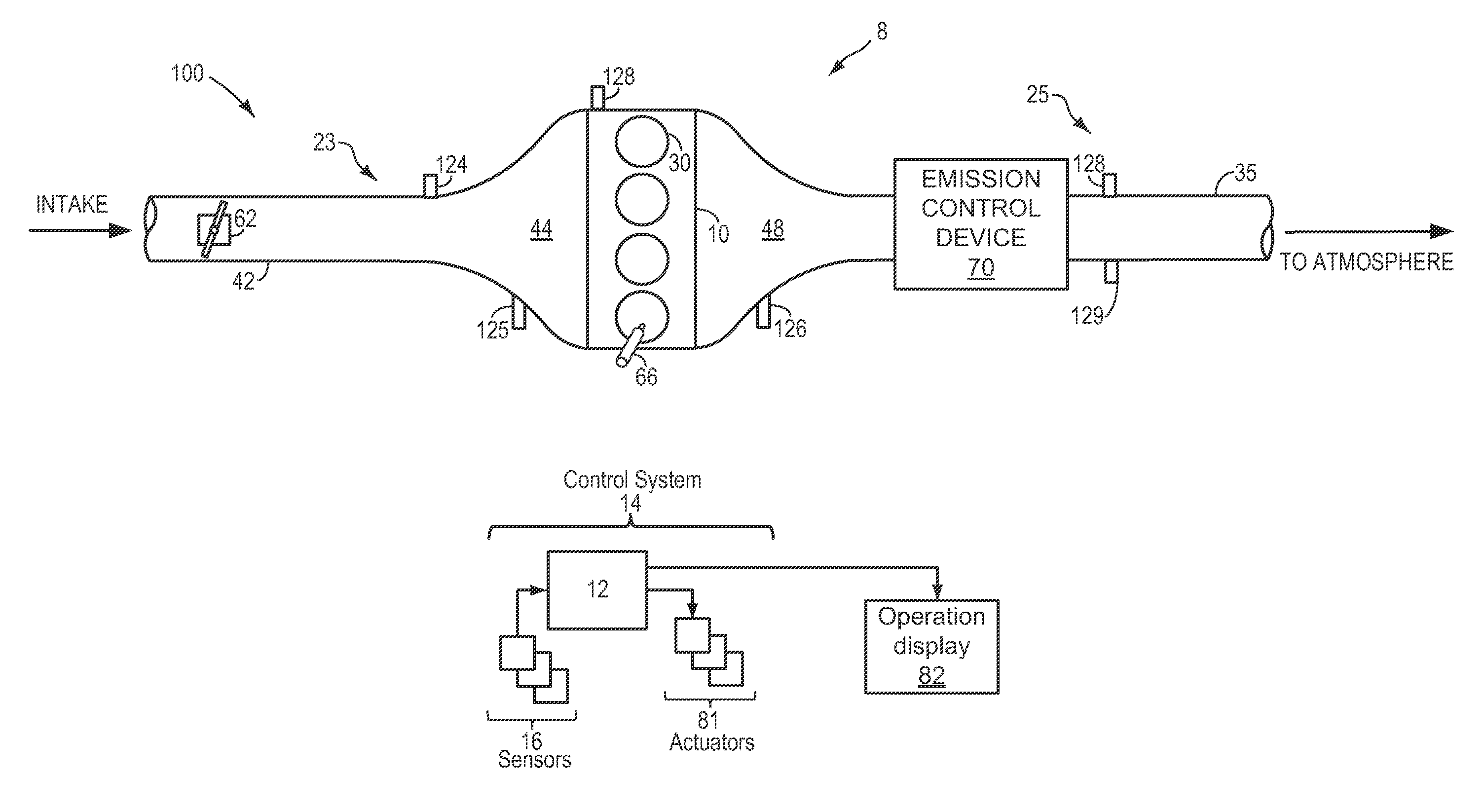
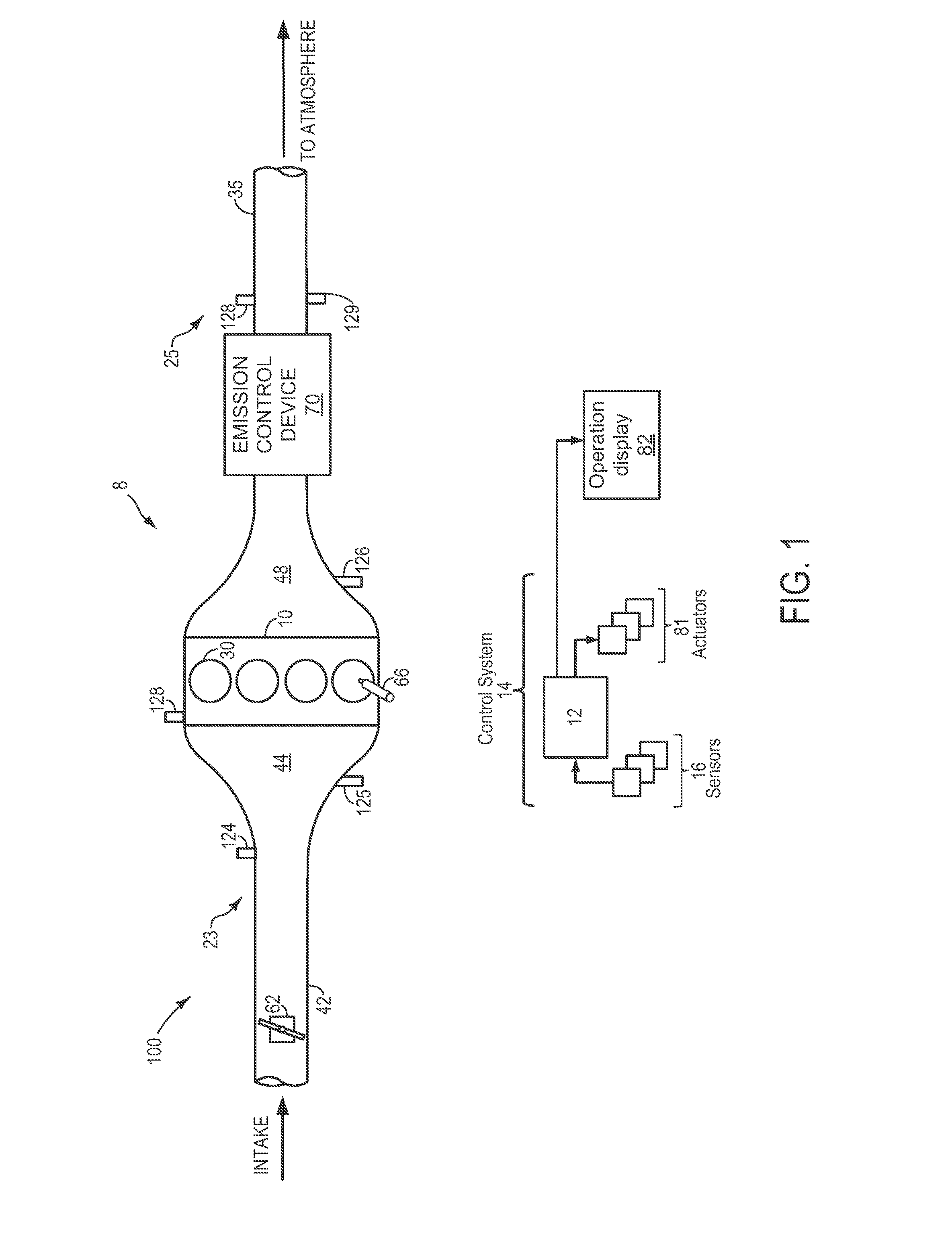
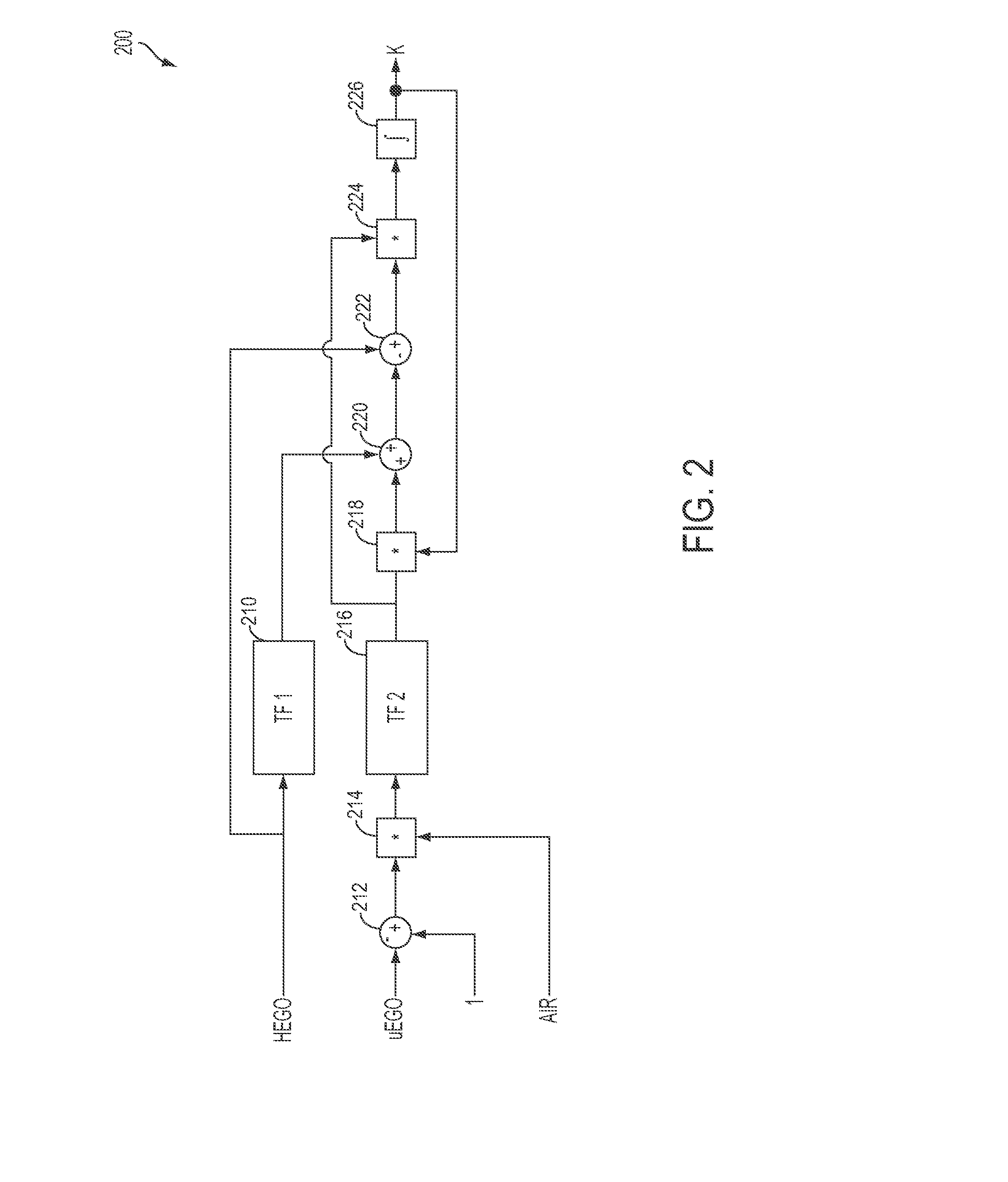
[0011]A support vector machine (SVM) may be used by a catalyst monitor to predict catalyst function. The SVM may be trained using pre-classified, known input parameters. During operation of a vehicle under selected conditions, various unclassified input parameters may be fed into the trained SVM model, and after a pre-defined number of samples have been classified, the total of each classification may be compared to a threshold to determine whether or not the catalyst is functioning. As example vehicle system including a catalyst is depicted in FIG. 1. Example control routines for determining an input parameter and operating the catalyst monitor are shown in FIGS. 2-4.

[0012]FIG. 1 shows a schematic depiction of a vehicle system 6. The vehicle system 6 includes an engine 10 having a plurality of cylinders 30. The engine 10 includes an intake 23 and an exhaust 25. The intake 23 includes a throttle 62 fluidly coupled to the engine intake manifold 44 via an intake passage 42. The exhaus...


PUM


Abstract

Embodiments for predicting catalyst function are disclosed. One example embodiment includes applying a set of parameter readings for a given sample to a support vector machine to generate a classification output, recording a plurality of classification outputs for a plurality of successive samples over a first duration, and indicating catalyst degradation if a threshold percentage of the classification outputs indicates degraded catalyst performance. In this way, catalyst degradation may be indicated using a simplified model that does not require extensive calibration.

Description


Claims


Application Information

Patent Timeline
Owner FORD GLOBAL TECH LLC
Why Eureka
Try Eureka