
Fuel cell system, electrode catalyst degradation judgment method, and moving body

a fuel cell and electrode catalyst technology, applied in the direction of cell components, instruments, electrochemical generators, etc., can solve the problem that the processing is not sufficient for diagnosis

Active Publication Date: 2010-05-06
TOYOTA JIDOSHA KK
View PDF4 Cites 14 Cited by
  • Summary
  • Abstract
  • Description
  • Claims
  • Application Information

AI Technical Summary

Benefits of technology

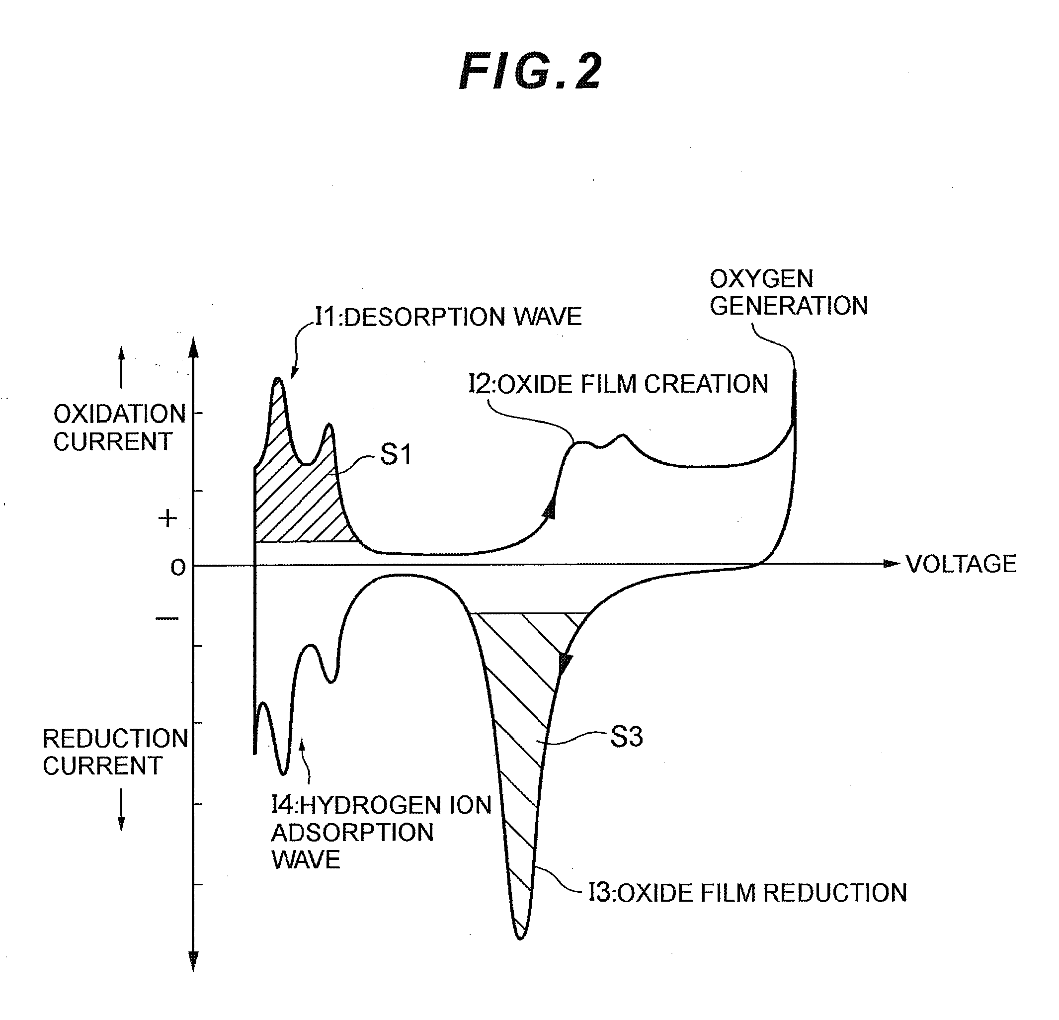
[0012]In this way, measurement of cyclic voltammetry (CV) is conducted so as to measure current while scanning applied voltage to the fuel cell repeatedly within a certain range under the condition where the electrode catalyst is activated, whereby a value corresponding to an effective area of the electrode catalyst associated with degradation of the electrode catalyst can be detected precisely, thus resulting in a precise decision whether the electrode catalyst is degraded or not.
[0015]With this configuration, the measurement of cyclic voltammetry (CV) under the condition that oxidation current flows through the fuel cell leads to a reaction of Pt.H→H++e− within a predetermined voltage range when Pt is used as electrode catalyst, and therefore when current obtained at this time is integrated, the electric quantity Q[C] associated with hydrogen desorption can be found, thus enabling a decision as to whether the electrode catalyst is degraded or not based on the electric quantity Q[C] associated with hydrogen desorption.
[0017]With this configuration, the measurement of cyclic voltammetry (CV) under the condition that reduction current flows through the fuel cell leads to a reaction of Pt.OH+2H++2e−→Pt+H2O as a reaction of OH− desorption within a predetermined voltage range, and therefore when current obtained at this time is integrated, the electric quantity Q[C] associated with water desorption can be found, thus enabling a precise decision as to whether the electrode catalyst is degraded or not based on the electric quantity Q[C] associated with water desorption.

Problems solved by technology

Such processing is not sufficient for a diagnosis as to whether the catalyst for each electrode is degraded or not.

Method used


Image

  • Fuel cell system, electrode catalyst degradation judgment method, and moving body
  • Fuel cell system, electrode catalyst degradation judgment method, and moving body
  • Fuel cell system, electrode catalyst degradation judgment method, and moving body

Examples


embodiment 1

[0027]The present embodiment describes an example where the present invention is adapted to a vehicle-mounted electric-power generation system for a fuel cell hybrid vehicle.

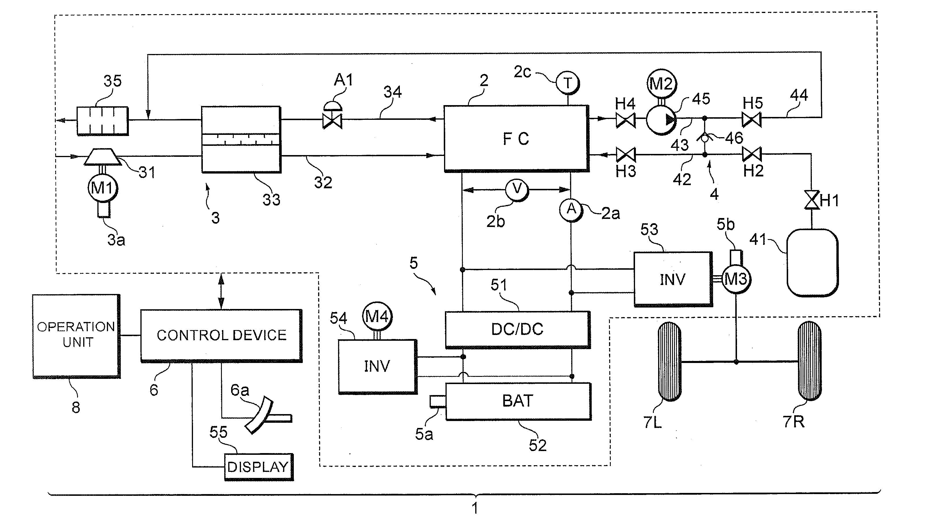
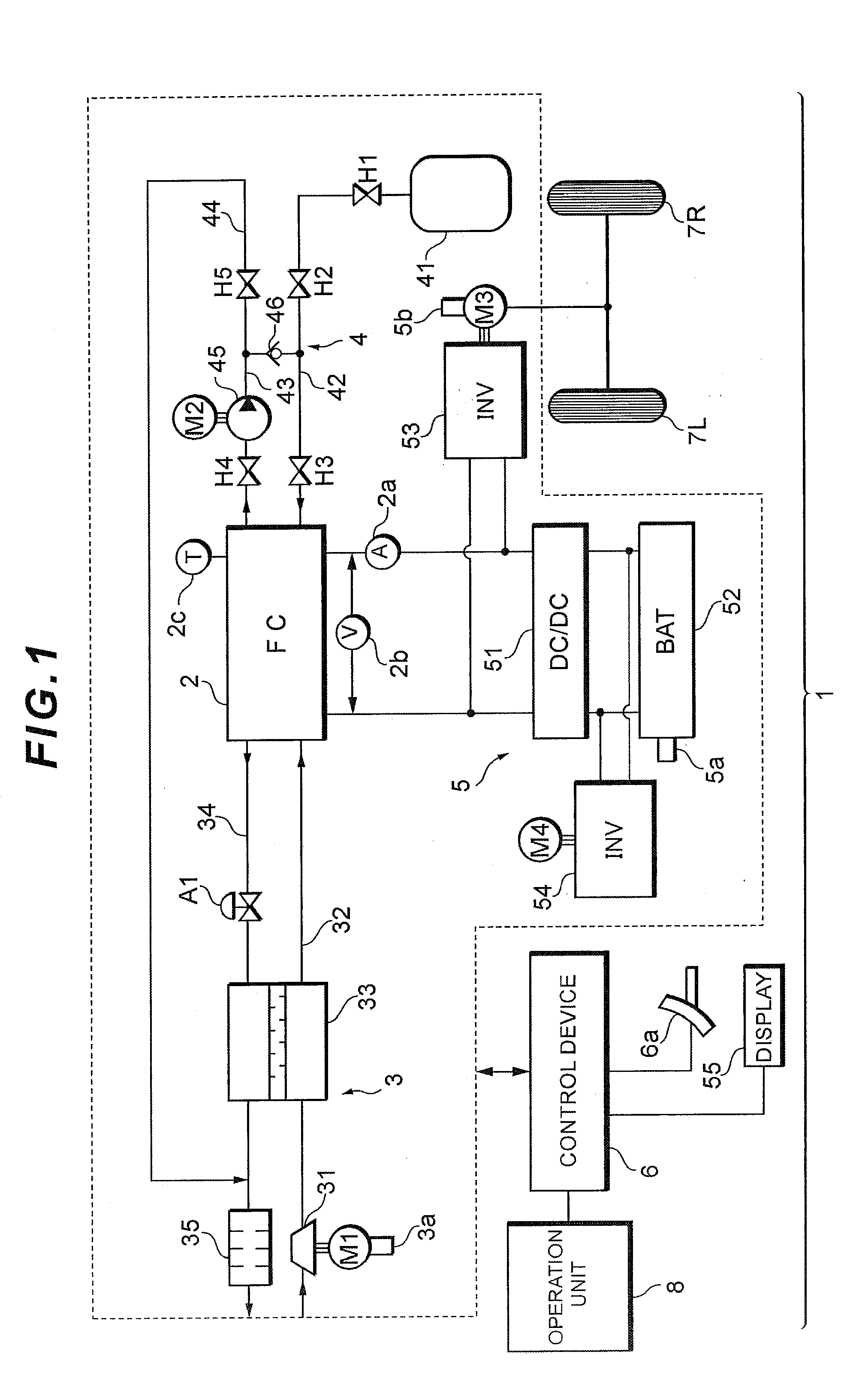
[0028]Referring now to FIG. 1, the configuration of a fuel cell system 1 according to the present embodiment will be described below.

[0029]As illustrated in FIG. 1, the fuel cell system 1 of the present embodiment includes a fuel cell 2 that generates electricity in response to supply of reaction gas (oxidation gas and fuel gas) and generates electric power from the electricity generation, an oxidation gas piping system 3 that supplies air as the oxidation gas to the fuel cell 2, a fuel gas piping system 4 that supplies hydrogen gas as the fuel gas to the fuel cell 2, an electric-power system 5 that charges and discharges electric power of the system, a control device 6 that controls the system as a whole, and the like.

[0030]The fuel cell 2, for example, is configured as a solid polymer electrolyte type, and inc...

embodiment 2

[0075]The above-stated Embodiment 1 describes the method of decreasing output voltage (overall voltage) of the fuel cell 2 for the measurement of the cyclic voltammetry (CV) to control the overall voltage over a predetermined range variably, thus detecting current in response to a change in the overall voltage. However, the measurement of cyclic voltammetry may be conducted based on detection voltage for each cell.

[0076]FIG. 4 illustrates a cell voltage monitor to implement Embodiment 2.

[0077]As illustrated in FIG. 4, Embodiment 2 is provided with a cell voltage monitor 56 that detects voltage of each cell included in a cell group making up the fuel cell 2, instead of the voltage sensor 2b.

[0078]Embodiment 2 operates for the measurement of cyclic voltammetry (CV) to detect output current of the fuel cell associated with a change in voltage of each cell by the above-stated current sensor 2a, for example, while monitoring the voltage of each cell detected by the cell voltage monitor ...

embodiment 3

[0081]In the above-stated Embodiment 1, an effective area is found by integration for a distinctive part of voltammogram obtained by the measurement of cyclic voltammetry (CV), which is then compared with a degradation decision value. On the other hand, in Embodiment 3, a decision is made based on an absolute value of output current as to whether electrode catalyst is degraded or not.

[0082]FIG. 5 illustrates a current-electrical potential curve (voltammogram) corresponding to the degree of oxidation of electrode catalyst.

[0083]As is evident from FIG. 5, it can be understood that absolute values of output current in characteristic I3 and characteristic I1 also greatly change as electrode catalyst is degraded. Thus, in Embodiment 3 an absolute value of output current is compared with a degradation decision value, so as to decide whether the electrode catalyst is degraded or not. To this end, the degradation decision value is set beforehand so as to decide whether the electrode catalys...


PUM


Abstract

Output voltage of a fuel cell 2 is decreased by a converter 51 to conduct an activation treatment to catalyst of the fuel cell 2, while measuring reduction current by a current sensor 2a while scanning output voltage of the fuel cell 2 over a certain range by the converter 51 as measurement of cyclic voltammetry under the condition that supply of oxidation gas to the fuel cell 2 is stopped from a compressor 31, and this measurement value is integrated by a control device 6. The control device 6 finds a charge amount of electrode catalyst of the fuel cell 2 based on this integration value, decides whether this charge amount is smaller or not than a degradation decision value, and displays this decision result on a display 55. A decision can be made precisely as to whether the electrode catalyst of the fuel cell is degraded or not.

Description

TECHNICAL FILED [0001]The present invention relates to a degradation judgment for electrode catalyst in a fuel cell system including a fuel cell that generates electricity by an electrochemical reaction between fuel gas and oxidation gas.BACKGROUND ART [0002]In a fuel cell system that generates electricity using an electrochemical reaction between fuel gas (hydrogen) and oxidation gas (oxygen), conditions to control an auxiliary device that supplies hydrogen and oxygen are set so that a predetermined output can be obtained from a fuel cell, having a problem that conductivity of electrolyte and activity of electrode catalyst, for example, are degraded over time, thus leading to a failure to obtain the predetermined output from the fuel cell.[0003]To cope with this, a device is proposed, which diagnoses a degradation state of a fuel cell based on a current / voltage characteristic and corrects conditions to control auxiliary devices based on a result of the diagnosis so that a system ef...

Claims


Application Information

Patent Timeline
IPC IPC(8): H01M8/04H01M4/00
CPCH01M8/04223H01M8/04238H01M8/04552H01M8/04582H01M8/04589H01M8/04649H01M8/04228H01M2250/20Y02T90/32H01M8/04559H01M8/04873H01M8/0488H01M8/04679Y02E60/50Y02T90/40
Inventor NOTO, HIRONORIMANABE, KOTA
Owner TOYOTA JIDOSHA KK
Learn More