Pneumatic Tire

a pneumatic tire and crown portion technology, applied in the field of pneumatic tires, can solve the problems of reducing heat generation and abrasion performance of pneumatic tires, and achieve the effects of low cooling effect, enhanced cooling effect of crown portions, and enhanced cut separation resistan

Inactive Publication Date: 2007-08-30
BRIDGESTONE CORP
View PDF10 Cites 64 Cited by
  • Summary
  • Abstract
  • Description
  • Claims
  • Application Information

AI Technical Summary

Benefits of technology

[0010] Moreover, when the length of the sub-thin groove is less than 100% of the circumferential length of the center block, a cooling effect becomes low, and when the length of the sub-thin groove exceeds 180%, rigidity of the block becomes low.
[0011] In accordance with the pneumatic tire according to the feature of the present invention, the at least one sub-thin groove is provided on the center block in the heavy-load radial tire for a construction vehicle, which has the column of the center blocks. Accordingly, the cooling effect for the crown portion is increased, and the cut separation resistance thereof can be enhanced.
[0014] Moreover, preferably, each of the center blocks is partitioned by the sub-thin groove into two sub-blocks having surface areas equivalent to each other, a starting edge and terminal edge of the sub-thin groove are offset from each other in the tire width direction in the one center block, each of lengths of treading side edges of the sub-blocks is 0.3 to 0.7 time a length of a trading side edge of the center block, and each of lengths of ejection side edges of the sub-blocks is 0.3 to 0.7 time a length of an ejecting side edge of the center block. Here, “offset” refers to that phases of the starting edge and the terminal edge are shifted from each other. Specifically, the starting edge and the terminal edge are not present on the same straight line parallel to the tire circumferential direction. As described above, the starting edge and terminal edge of the sub-thin groove are offset from each other in the tire width direction, and accordingly, an intersection point of the grooves can be avoided being formed, and a small stone can be prevented from intruding into the groove.
[0015] Furthermore, the center block is divided into the sub-blocks at the positions where the lengths of the sub-blocks are 0.3 to 0.7 time the length of the center block. This is because, when the center block is divided at an end portion of the center block, rigidity of the sub-blocks is decreased.
[0017] Furthermore, it is preferable that the starting edge of the sub-thin groove of the one center block and a terminal edge of a sub-thin groove of a center block adjacent to the one center block concerned in the circumferential direction be offset from each other in the tire width direction. By the fact that the starting edge and the terminal edge are offset from each other in the tire width direction, the intersection point of the grooves can be avoided being formed, and the small stone can be prevented from intruding into the groove.

Problems solved by technology

Moreover, when the negative ratio in the tread contact width is less than 15%, it is difficult to reduce the heat generation, and when the negative ratio in the tread contact width exceeds 30%, a problem occurs in abrasion performance of the pneumatic tire.

Method used


Image

  • Pneumatic Tire
  • Pneumatic Tire
  • Pneumatic Tire

Examples


example

[0047] A description will be made of the present invention more in detail by mentioning an example below. However, the present invention is not limited to the following example at all.

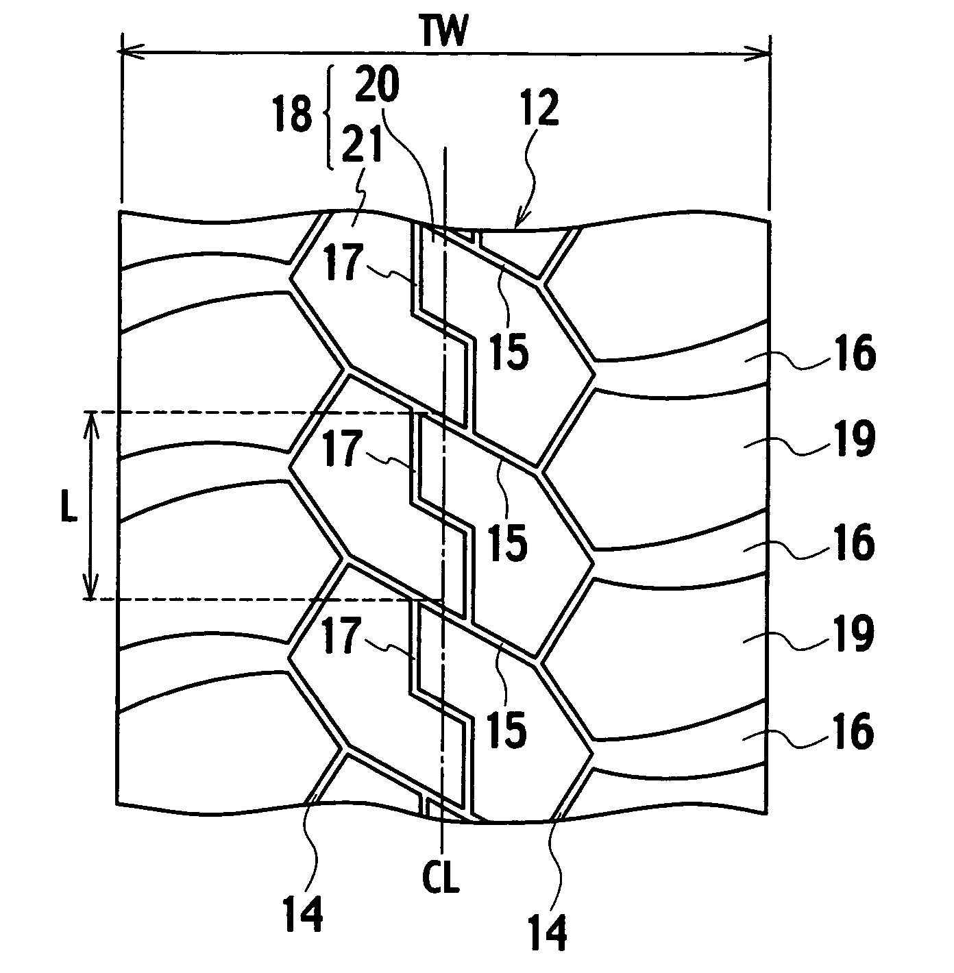
[0048] In order to confirm the effect of the present invention, one type of the tire of the example to which the present invention is applied and two types of tires of conventional examples were manufactured, and the heat generation resistance of the tread portion of each of the tires was investigated. In both of the example and the comparative examples, a tire size was 46 / 90R57. Tread patterns of Example 1, Conventional example 1, and Conventional example 2, which are as described above, were as shown in FIG. 1, FIG. 7, and FIG. 8, respectively.

[0049] The heat generation resistance of each tread portion was evaluated in such a manner that the tire was attached onto a design rim defined in the TRA and an off-the-road drum test was performed under conditions where an air pressure was 7.0 kgf / cm2 and a...


PUM


Abstract

A pneumatic tire includes a column of center blocks (18) partitioned, on a tread center region, by circumferential thin grooves (14) formed along a tire circumferential direction and crosswise thin grooves (15) formed along a tire width direction, and columns of shoulder blocks (19) partitioned by the circumferential thin grooves (14) and main rag grooves (16) on shoulder portions. Each of the center blocks (18) includes one or more sub-thin grooves (17); each of which has a length of 100 to 180% of a circumferential length of the center block (18)

Description

TECHNICAL FIELD [0001] The present invention relates to a pneumatic tire excellent in heat generation resistance, and particularly to an off-the-road pneumatic tire for a heavy load in a construction vehicle category. BACKGROUND ART [0002] Heretofore, in an off-the-road pneumatic tire, there has been a case where a belt of a crown portion is cut because the crown portion treads on an obstacle such as a rock. During running, a crack advances into rubber of the pneumatic tire from such a cut portion as describe above, a cracked portion of the rubber is peeled off, and the pneumatic tire has thereby become junk. As a past accomplishment, by enhancing heat generation property of the rubber, the crack became difficult to advance even if the portion of the belt was cut. Accordingly, a reduction of the heat generation in tread rubber has been promoted. [0003] For example, there is disclosed a technology for extending an entire running period of the pneumatic tire by employing tread rubber ...

Claims


Application Information

Patent Timeline
Patent Type & Authority Applications(United States)
IPC IPC(8): B60C11/12
CPCB60C11/0311Y10S152/902B60C2200/065B60C11/033Y10S152/03
Inventor HAYASHI, HIROSHI
Owner BRIDGESTONE CORP
Why Eureka
Try Eureka