Speaker system with broad directivity

Inactive Publication Date: 2007-08-30
YAMAHA CORP
View PDF11 Cites 3 Cited by
  • Summary
  • Abstract
  • Description
  • Claims
  • Application Information

AI Technical Summary

Benefits of technology

[0027]Accordingly, in addition to the first acoustic path and the second acoustic path, by adding the third acoustic path formed by the hole, the number of the acoustic paths generating path difference is increased, so that a peak and a dip generated at a specific frequency can be moderated by the phase interference.
[0028]In this manner, in accordance with the present invention, the broad directivity can be achieved with respect to the range from the low frequency to the relatively high frequency without causing the decrease of the output in the relatively high frequency range. Accordingly, the cone type speaker unit with large diameter can be i

Problems solved by technology

However, as the diameter of the speaker is larger, a problem of directivity arises.
Thus, when the cone type speaker with large diameter is mounted to a ceiling, the sound is clear right under the cone type speaker, but as being distant therefrom, the sound becomes hollow and unclear.
However, the transducing efficiency is deteriorated.
However, when the cone type speaker with large diameter is used as a woofer and the high frequency speaker is set to output the sound of high frequency higher than a crossover frequency, no problem occurs at the central axis (0°),

Method used


Image

  • Speaker system with broad directivity
  • Speaker system with broad directivity
  • Speaker system with broad directivity

Examples


first embodiment

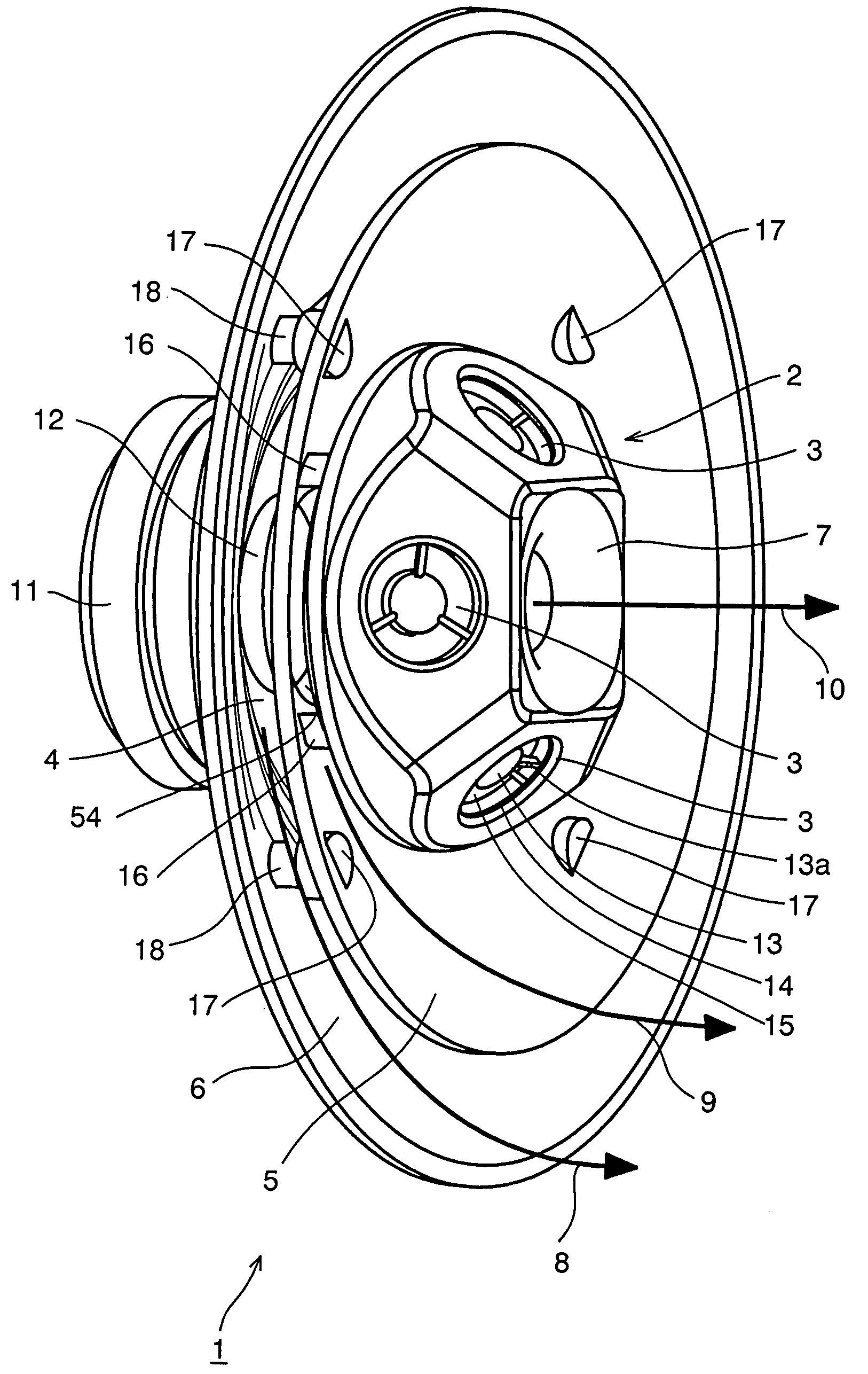
[0038]FIG. 1 is a perspective view showing the present invention.

[0039]A reference numeral 1 indicates a cone type speaker unit, which plays a role of outputting sound ranging from a low frequency to a relatively high frequency, i.e., corresponds to a “woofer”. In order to increase a transducing efficiency, a diameter of the cone type speaker may be increased over 6.5 inch (16.5 cm). It is preferable that the diameter is about 8 inch (20.32 cm).

[0040]A reference numeral 2 is a diffuser. It is depicted in the drawing that high frequency speaker units 3 are mounted to an outer peripheral surface 57 (see FIG. 4) of the diffuser 2, however, this is not an indispensable structure. The high frequency speaker unit 3 plays a role of outputting high frequency sound, i.e., corresponds to a “tweeter”. It is depicted in the drawing that four units are arranged equi-angularly with each other.

[0041]A reference numeral 4 is a cone type vibration plate of the speaker unit 1. A typical cross-section...

second embodiment

[0103]FIG. 5 is a sectional structure view showing present invention.

[0104]In the drawing, the same elements as FIGS. 1 to 4 are denoted by the same reference numerals, and detailed description thereof will be omitted.

[0105]In this embodiment, the flange 28 of the cone type speaker unit 1 is mounted to a horn-shaped baffle plate 61. The horn-shaped baffle plate 61 has a conical horn shape. It is preferable that an inner surface B of the horn-shaped baffle plate 61 expands along the outer surface A of the first horn 5 (see FIG. 4).

[0106]Functionally, the horn-shaped baffle plate 61 can substitute for the second horn 6 described with reference to FIGS. 1 to 4. In addition, the horn-shaped baffle plate 61 has a function as a baffle for preventing the sound emitted from the outer surface A of the cone type vibration plate 4 (see FIG. 4) from turning back to the front surface.

[0107]A reference numeral 63 is a self tap boss, which is previously fixed to the flange 28 by a predetermined fi...

third embodiment

[0108]FIG. 6 is a sectional structure view showing present invention. In the drawing, the same elements as FIGS. 1 to 5 are denoted by the same reference numerals, and detailed description thereof will be omitted.

[0109]In this embodiment, instead of the cone type speaker unit 1 depicted in FIGS. 1 to 5, a speaker unit 71 having a non-cone type vibration plate is used. The non-cone type vibration plate is also driven by the voice coil of the magnetic circuit unit.

[0110]A speaker unit having a dome type vibration plate, a speaker unit having a plane type vibration plate or the like can be used as the speaker unit 71 having the non-cone type vibration plate.

[0111]In this embodiment, a second horn 72 substitutes for the cone type vibration plate 4 depicted in FIGS. 1 to 4. The second horn 72 is configured as if the small-diameter opening 52 (see FIG. 4) of the second horn 6 depicted in FIGS. 1 to 4 is extended to an opening 71a of the speaker unit 71 and mounted to the speaker unit 71 h...


PUM


Abstract

A speaker system has a speaker unit with a vibration plate of a corn type, a horn and a diffuser. The horn is disposed such that a small-diameter opening thereof is positioned inward from a front opening of the vibration plate, and an outer surface of the horn is arranged along an inner surface of the vibration plate from the small-diameter opening to form a first acoustic path. The diffuser has a base portion, a front end portion and an outer peripheral surface extending therebetween, and is disposed such that the base portion is positioned inward from a front opening of the horn and opposed to the small-diameter opening of the horn. The diffuser has a specific shape such that the outer peripheral surface expands along an inner surface of the horn from the base portion to form a second acoustic path. The expanding outer peripheral surface of the diffuser is then narrowed toward the front end portion of the diffuser.

Description

BACKGROUND OF THE INVENTION[0001]1. Technical Field of the Invention[0002]The present invention relates to a speaker system with broad directivity which can achieve broad band directivity ranging from a low frequency to a relatively high frequency.[0003]2. Description of the Related Art[0004]In a speaker system mounted to a ceiling or the like, a cone type speaker is generally used in a unitary body. In order to increase electric-acoustic transducing efficiency, there may be a demand of desiring to use the cone type speaker with large diameter (over about 6.5 inch or 16.5 cm). However, as the diameter of the speaker is larger, a problem of directivity arises.[0005]FIG. 7 is a view showing a feature of a conventional cone type speaker with large diameter.[0006]FIG. 7(a) is a graph showing a directivity when a conventional cone type speaker with large diameter is used. FIG. 7(b) is a graph showing a frequency response when a high frequency speaker is combined with a conventional cone ...

Claims


Application Information

Patent Timeline
IPC IPC(8): H05K5/00
CPCH04R1/24H04R2201/021H04R1/403H04R1/345
Inventor IWAYAMA, KEN
Owner YAMAHA CORP
Why Eureka
Try Eureka