
Drive device of color LED backlight

a technology of driving device and color light, which is applied in the direction of electric variable regulation, process and machine control, instruments, etc., can solve the problems of inability to achieve accurate color reproduction and severe competition among enterprises for improving the price and performance of tft-lcd, and achieve the effect of high production efficiency and easy chang

Inactive Publication Date: 2007-08-30
SAMSUNG ELECTRONICS CO LTD
View PDF17 Cites 95 Cited by
  • Summary
  • Abstract
  • Description
  • Claims
  • Application Information

AI Technical Summary

Benefits of technology

The present invention provides a drive device for a color LED backlight with high production efficiency. The device can uniformly control the optical output of the LED regardless of changes in ambient temperature and can easily change the characteristic data of the LED upon replacement without the need for an additional external circuit. The device includes a voltage detecting unit, a temperature detecting unit, a control unit, and a multi-channel current source. The control unit uses a lookup table to adjust the driving currents in the LED arrays based on the detected temperature and voltage. The multi-channel current source adjusts the driving currents through a current converter and current sources for each color LED array. The technical effects of the invention include improved production efficiency, uniform control of LED output, and easy replacement of LED without additional circuits.

Problems solved by technology

Competition among enterprises for improvement of price and performance of the TFT-LCD is becoming severe.
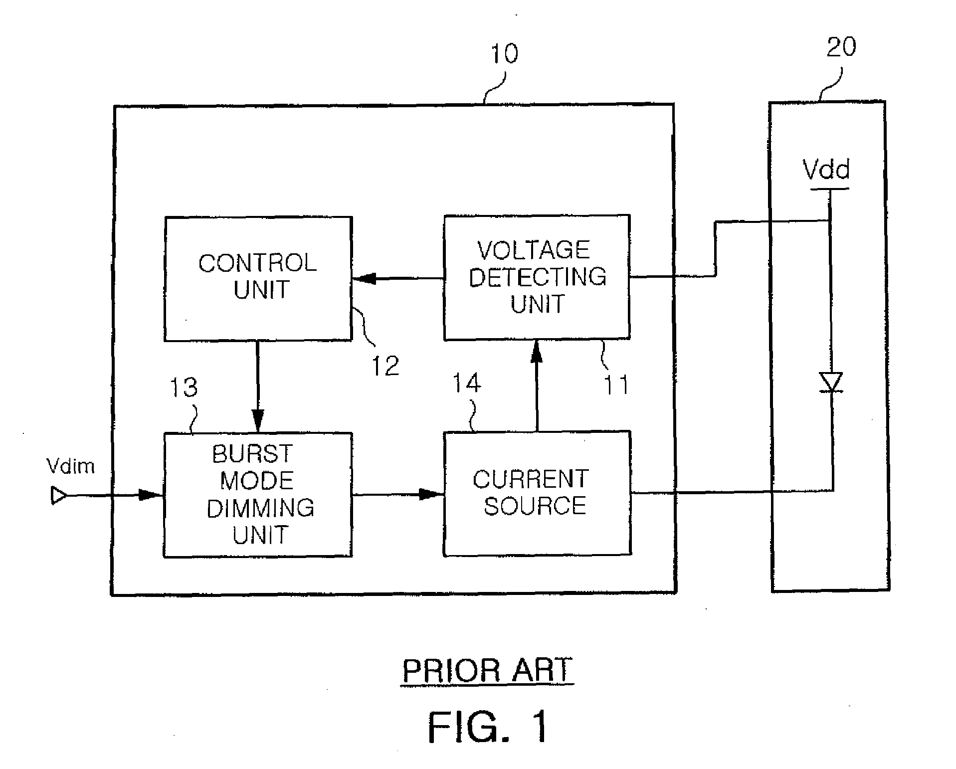
However, since the CCFL is weak against external impact, a mobile TFT-LCD having a size of about 5 inches or less uses a white LED.
In the CCFL or the white LED, since color reproducibility falls to about 70 to 80% of the NTSC standard, it is impossible to accomplish accurate color reproduction.

Method used


Image

  • Drive device of color LED backlight
  • Drive device of color LED backlight
  • Drive device of color LED backlight

Examples


Embodiment Construction

[0021]Now, preferred embodiments of the present invention will be described in detail with reference to the annexed drawings. In the drawings, the same or similar elements are denoted by the same reference numerals even though they are depicted in different drawings.

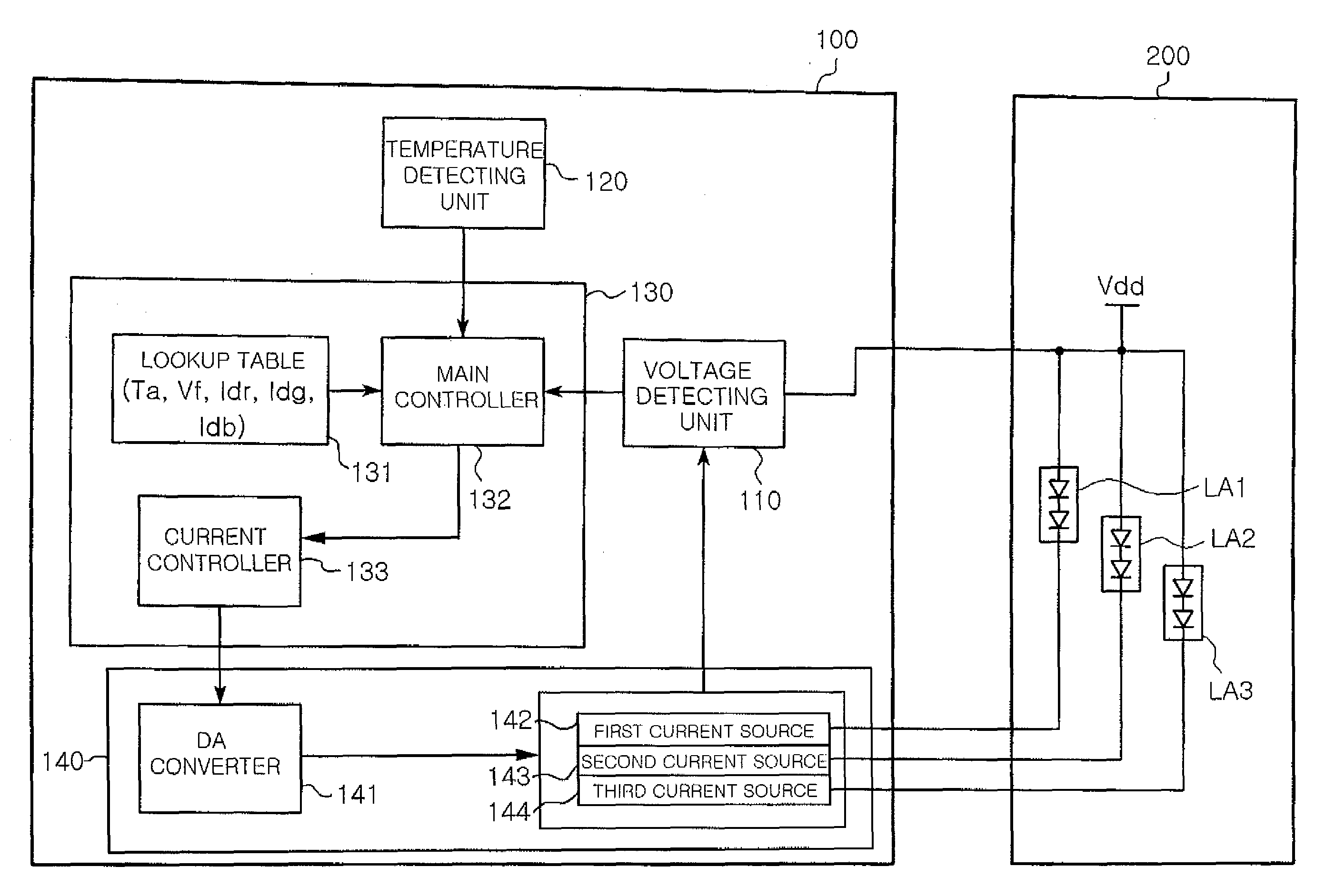
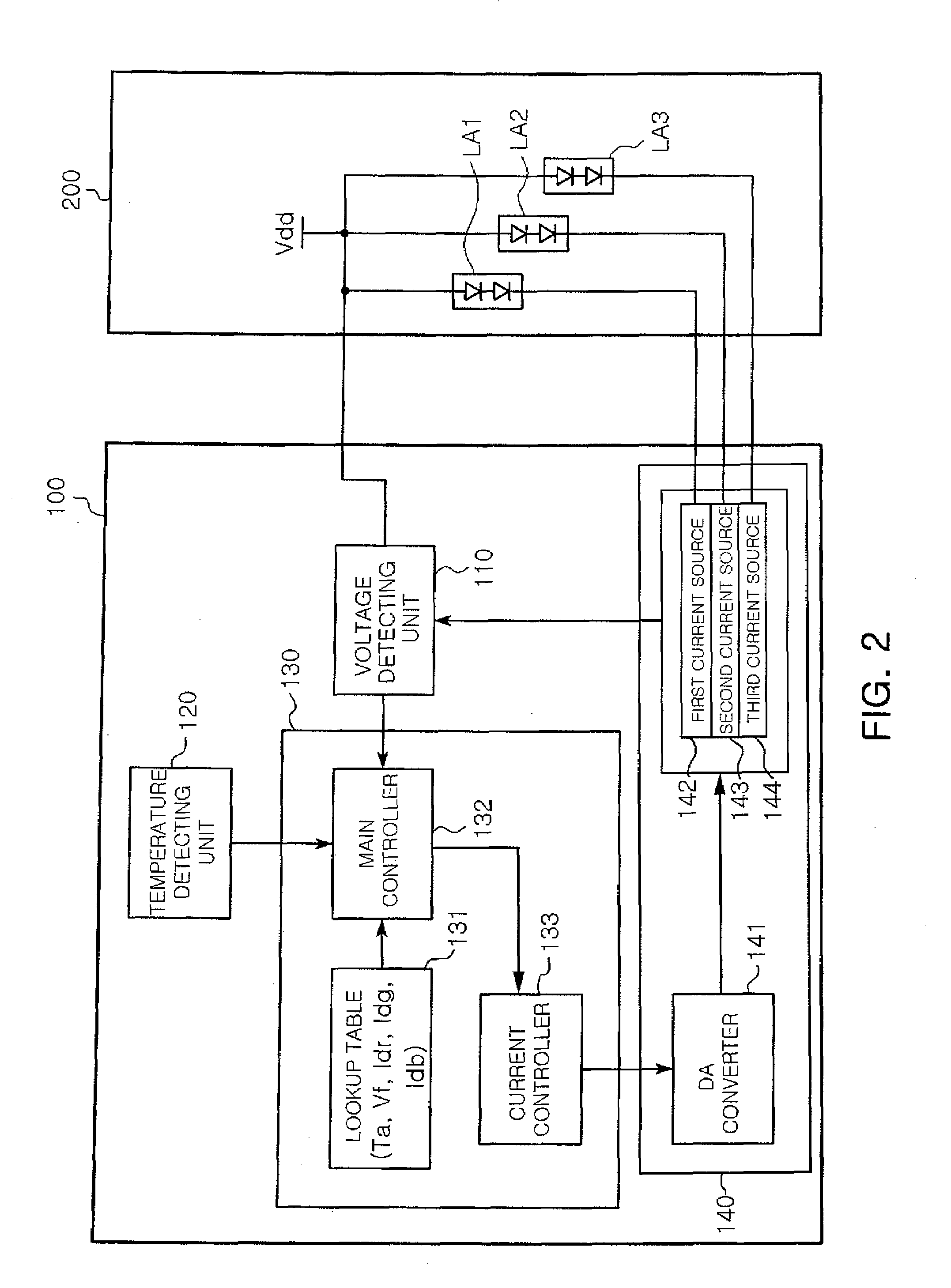
[0022]FIG. 2 is a block diagram showing the configuration of a drive device of a color LED backlight according to the present invention.

[0023]Referring to FIG. 2, the drive device of the color LED backlight according to the present invention drives a color LED backlight 200 including a plurality of color LED arrays LA1, LA2 and LA3 and includes a voltage detecting unit 110, a temperature detecting unit 120, a control unit 130 and a multi-channel current source 140.

[0024]The voltage detecting unit 110 detects a voltage applied to the white LED backlight 200, that is, a forward voltage.

[0025]The temperature detecting unit 120 detects the temperature of the color LED backlight 200. Since light efficiencies of color LEDs inc...


PUM


Abstract

Disclosed herein is a drive device of a color light emitting diode (LED) backlight, which is capable of uniformly controlling an optical output of an LED regardless of a variation in an ambient temperature and easily changing characteristic data (by referring to a lookup table).The drive device for driving the color LED backlight which includes a plurality of color LED arrays includes a voltage detecting unit for detecting a voltage applied to the color LED backlight, a temperature detecting unit for detecting a temperature of the color LED backlight, a control unit for controlling driving currents which respectively flow in the color LED arrays of the color LED backlight according to the temperature detected by the temperature detecting unit and the voltage detected by the voltage detecting unit, by referring to previously set driving current values, and a multi-channel current source for adjusting amounts of the driving currents which respectively flow in the color LED arrays of the color LED backlight, by the driving current control of the control unit.

Description

RELATED APPLICATIONS[0001]The present application is based on, and claims priority from, Korean Application Number 2006-19405, filed Feb. 28, 2006, the disclosure of which is incorporated by reference herein in its entirety.BACKGROUND OF THE INVENTION[0002]1. Field of the Invention[0003]The present invention relates to a drive device of a color light emitting diode (LED) used in a display apparatus, and more particularly, to a drive device of a LED backlight with high production efficiency, which is capable of uniformly controlling an optical output of an LED regardless of a variation in an ambient temperature and changing the characteristic data without an additional external circuit upon replacement of the LED, by controlling the optical output amounts of color LED arrays according to the ambient temperature of the LED or a detection voltage of the LED and easily changing characteristic data upon replacement of the LED.[0004]2. Description of the Related Art[0005]In general, at le...

Claims


Application Information

Patent Timeline
Patent Type & Authority Applications(United States)
IPC IPC(8): H05B39/04H05B44/00
CPCH05B33/0827H05B33/0854H05B33/0851H05B45/46H05B45/18
Inventor HA, CHANG WOOMIN, BYOUNG OWNGONG, JUNG CHUL
Owner SAMSUNG ELECTRONICS CO LTD
Learn More