Regulated power supply with multiple regulators sharing the total current supplied to a load

Active Publication Date: 2007-08-30
INFINEON TECH AUSTRIA AG
View PDF22 Cites 70 Cited by
  • Summary
  • Abstract
  • Description
  • Claims
  • Application Information

AI Technical Summary

Benefits of technology

[0013] In accordance with one aspect of the invention, it was recognized that multiple regulators provided different levels of current to the load. This could occur for various reasons such as component mismatch, components aging d

Problems solved by technology

This could occur for various reasons such as component mismatch, comp

Method used


Image

  • Regulated power supply with multiple regulators sharing the total current supplied to a load
  • Regulated power supply with multiple regulators sharing the total current supplied to a load
  • Regulated power supply with multiple regulators sharing the total current supplied to a load

Examples


Embodiment Construction

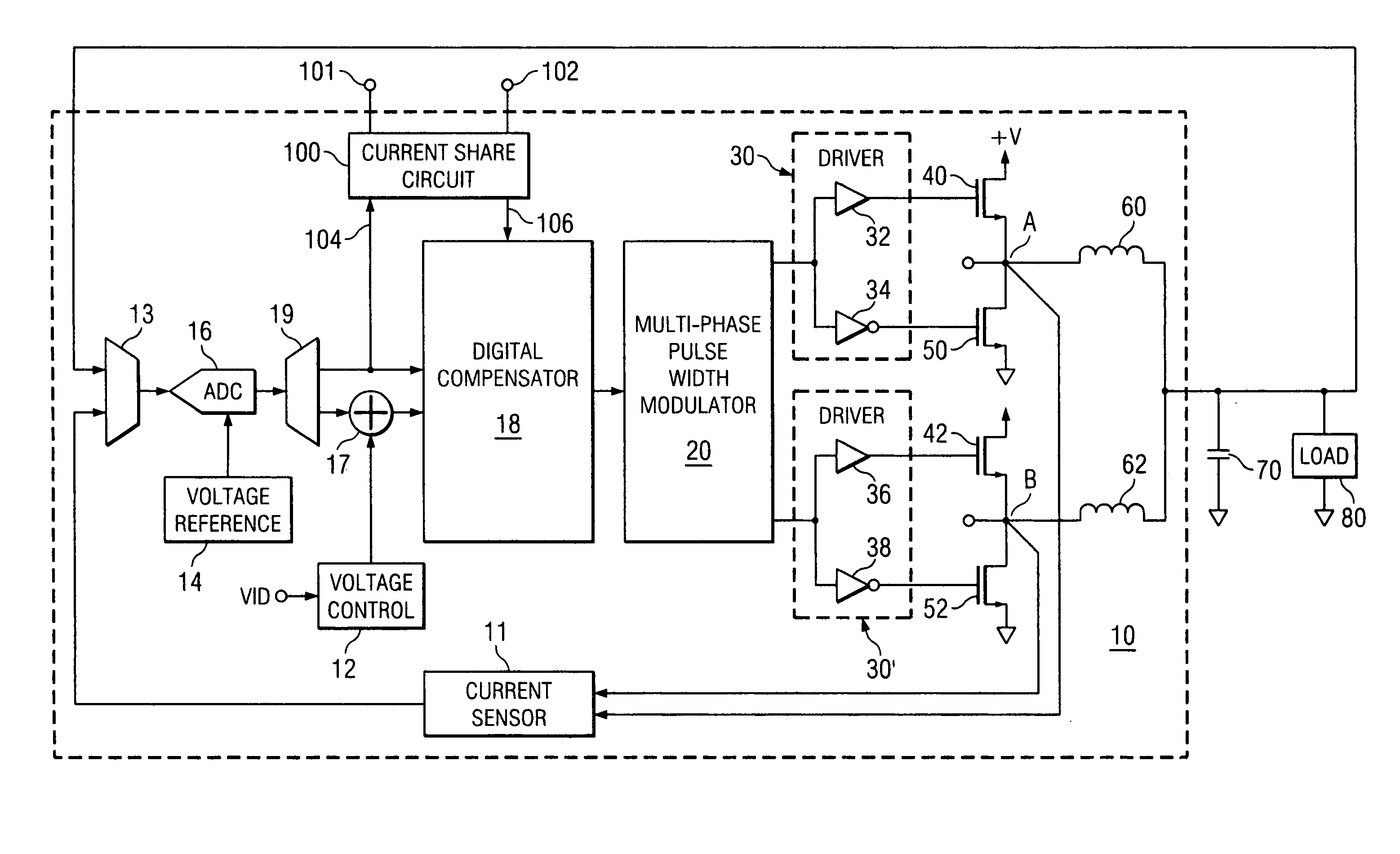
[0034] Refer now to FIG. 1, for a block diagram illustrating a switched power converter, i.e. regulator, incorporating the current sharing circuit 100 in accordance with one aspect of the invention. The regulator 10 (without the current sharing circuit 100) has previously been described in detail, for example, in the cross-referenced patent applications that have been incorporated herein by reference. This type of regulator is also known as a Buck Converter or Multiphase Buck Converter and it converts a relatively high supply potential (+V) at e.g. 12 volts to a low voltage, e.g. 1 to 3 volts that is provided at very high current levels to a load. Regulator 10 is shown including Single or Multi-phase Pulse Width Modulator (PWM) 20.

[0035] The output of PWM 20 is a series of pulses on each of its output lines, the phase 1 output being provided to the driver In power stage 30 and the phase 2 output being provided to the driver circuit in power stage 30′. In a multi-phase system having...


PUM


Abstract

Disclosed is a digital current sharing structure and method in which a plurality of regulators are configured to share the load current. Current share circuits in each of the regulators are configured to measure and compare the average current provided by that particular regulator with the overall average current provided by all the regulators. Each of the current share circuits then provides an output so that the output of each regulator is adjusted to provide the same amount of current to the load. Digital processing with both analog and digital averaging are disclosed. Also disclosed is a programmable hysteresis technique to eliminate relatively trivial adjustments.

Description

CROSS REFERENCES TO RELATED US PATENT APPLICATIONS AND PATENTS [0001] 1. SYSTEM AND METHOD FOR HIGHLY PHASED POWER REGULATION, Ser. No. 10 / 112,738 filed Apr. 1, 2002, inventors: Duffy, et al, now U.S. Pat. No. 6,563,294. [0002] 2. SYSTEM, DEVICE AND METHOD FOR PROVIDING VOLTAGE REGULATION TO A MICROELECTRONIC DEVICE, Ser. No. 10 / 103,980, filed Mar. 22, 2002, inventors: Duffy et al, now U.S. Pat. No. 6,965,502. [0003] 3. SYSTEM AND METHOD FOR CURRENT HANDLING IN A DIGITALLY CONTROLLED POWER CONVERTER, Ser. No. 10 / 237,903, filed Sep. 9, 2002, inventors: Duffy et al, now U.S. Pat. No. 6,795,009. [0004] 4. SYSTEM AND METHOD FOR HIGHLY PHASED POWER REGULATION USING ADAPTIVE COMPENSATION CONTROL, Ser. No. 10 / 109,801, filed Oct. 15, 2001, inventors: Goodfellow et al., now U.S. Pat. No. 7,007,176. [0005] 5. DIGITAL CALIBRATION WITH LOSSLESS SENSING IN A MULTIPHASE SWITCHED POWER CONVERTER, Ser. No. 10 / 884,840, filed Jul. 2, 2004, inventors: Southwell et al [0006] 6. MULTI-THRESHOLD MULTI-GA...

Claims


Application Information

Patent Timeline
IPC IPC(8): G05F1/00
CPCH02M3/157H02M3/158H02M3/1584
Inventor TANG, BENJAMINSOUTHWELL, SCOTT WILSONOSTROM, KENNETH A.
Owner INFINEON TECH AUSTRIA AG
Why Eureka
Try Eureka