Droplet discharging head, droplet discharging device and functional-film forming device

a technology of droplet discharge and droplet, which is applied in the direction of printing, etc., can solve the problems of reducing and achieve the effects of improving the landing precision of the droplet discharge, high viscosity, and enhancing the landing precision

Inactive Publication Date: 2007-08-30
SEIKO EPSON CORP
View PDF3 Cites 16 Cited by
  • Summary
  • Abstract
  • Description
  • Claims
  • Application Information

AI Technical Summary

Benefits of technology

[0006]An advantage of the present invention is to provide a droplet discharging head, a droplet discharging device and a functional-film forming device that are capable of enhancing the landing precision.
[0007]A droplet discharging head according to a first aspect of the invention includes a first through hole having an outlet for discharging of a liquid material and a second through hole having an inlet for injection of the liquid material. The second through hole is provided with protrusions on its surface.
[0008]A droplet discharging head according to a second aspect of the invention includes (1) a base body that includes a cavity for holding of a liquid material and a nozzle portion for discharging of the liquid material from the cavity, the cavity and the nozzle portion having been formed in the base body, and (2) a control portion that is placed on the cavity and controls the discharging of the liquid material. The nozzle portion includes a first through hole with an outlet for discharging of the liquid material and a second through hole with an inlet for injection thereof. The second through hole has a plurality of protrusions formed on its surface.
[0009]This enhances, through the rectifying effect of the protrusions, the straight moving property of the liquid material flowing in the nozzle portion, thereby improving the landing precision of the droplets discharged from the outlet even in cases where the liquid material being discharged has a relatively high viscosity, as in the case of an organic solvent, a high polymer material, or the like.
[0010]In the above droplet discharging head, it is preferable that the sectional area of the protrusions be larger toward the outlet than toward the inlet. This enhances the rectifying effect.
[0011]In the above droplet discharging head, it is preferable that the second through hole have a tapered shape.

Problems solved by technology

However, when viscosity increases in a liquid material discharged from the droplet discharging device, the straight moving property of the discharged droplet deteriorates, thus reducing its landing precision.

Method used


Image

  • Droplet discharging head, droplet discharging device and functional-film forming device
  • Droplet discharging head, droplet discharging device and functional-film forming device
  • Droplet discharging head, droplet discharging device and functional-film forming device

Examples


first embodiment

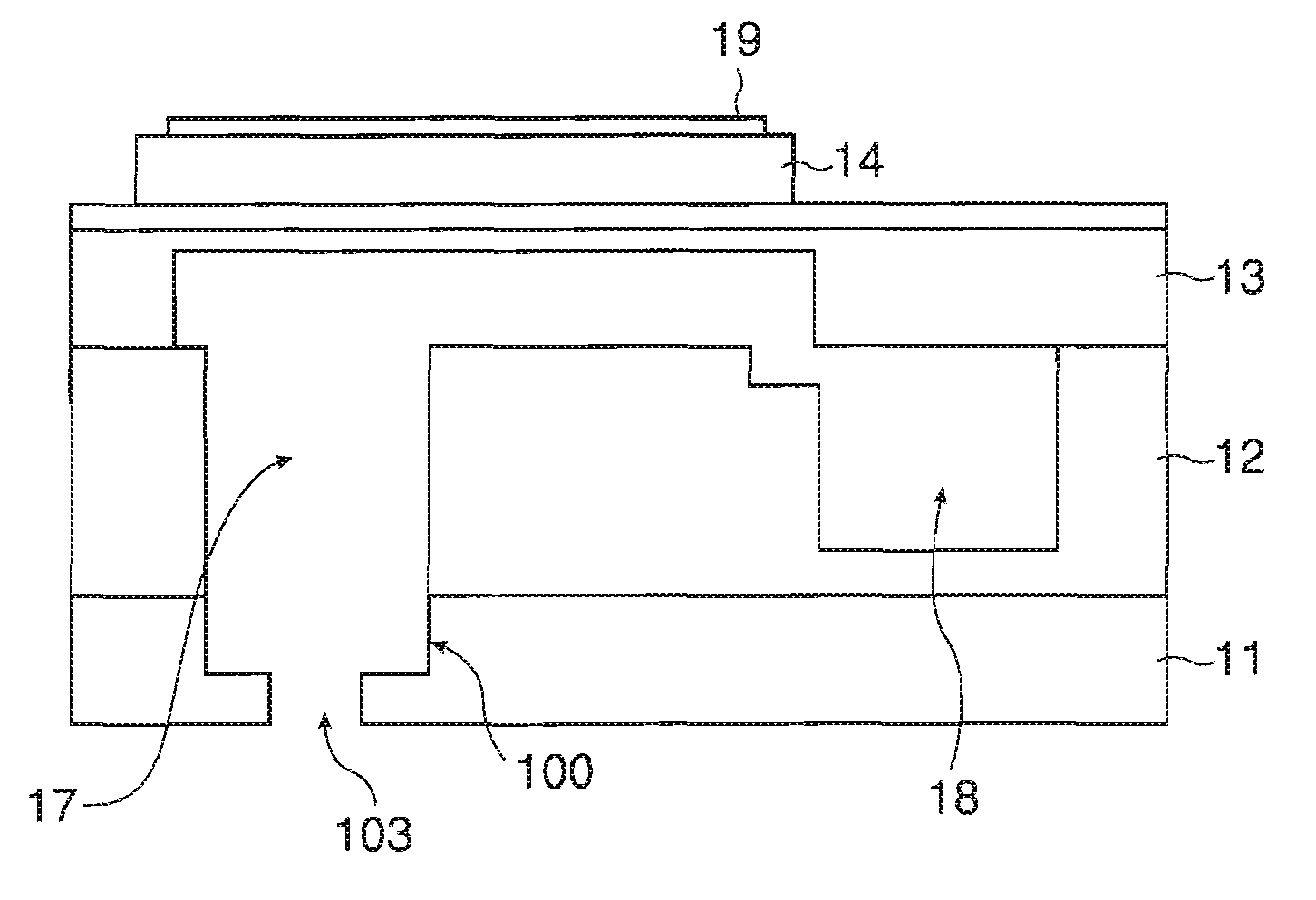
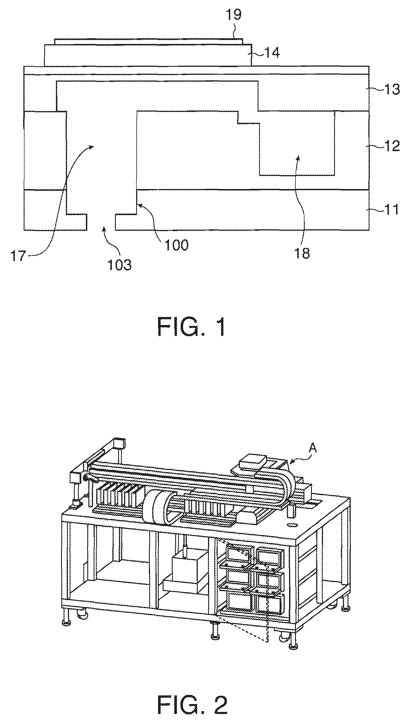
[0042]FIG. 1 schematically shows the structure of a droplet discharging head 10 according to a first embodiment of the invention in its sectional view

[0043]As shown in FIG. 1, the droplet discharging head 10 is provided with a nozzle plate 11, a flow path substrate 12, a diaphragm 13, a piezo (piezoelectric element) 14 and an electrode 19. For example, a nozzle portion 100 is formed in the nozzle plate 11 while a cavity 17 and a reservoir 18 are formed in the flow path substrate 12. The nozzle plate 11 and the flow path substrate 12 may be formed either separately or integrally.

[0044]Here, the nozzle portion 100 represents part of a base body having a structure to discharge a liquid material, which includes the nozzle plate 11, and mainly refers to the part which the liquid material lastly passes through before it is discharged. It does not always take the form of a through hole, but in FIG. 1 it forms a through hole.

[0045]On the other hand, the cavity 17 represents part of a base b...

second embodiment

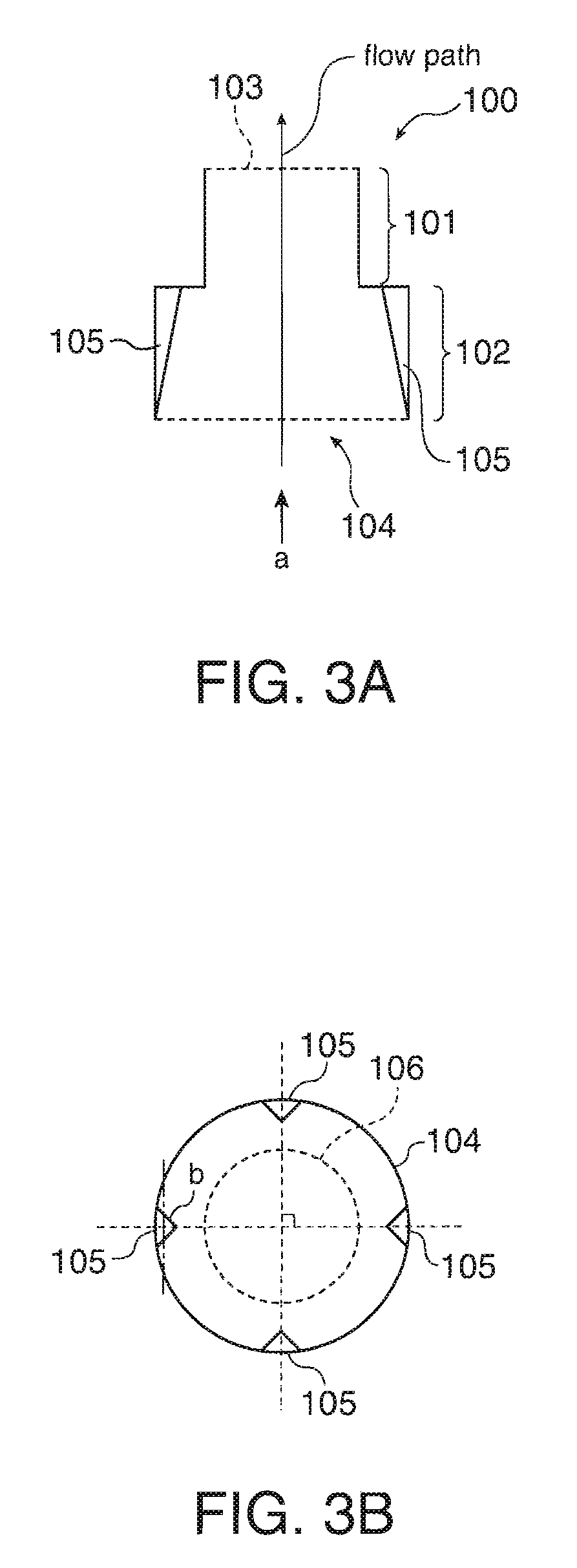
[0060]FIGS. 5A and 5B show the shape of the nozzle portion 100 of the droplet discharging head 101 in its sectional views. FIG. 5A is a schematic of its section that is parallel to the flow path of the liquid material and FIG. 5B is a plan view of its cross section observed from the direction a shown in FIG. 5A.

[0061]In the second embodiment, the protrusions 105 are provided on the inside wall of the outer nozzle hole 101 in the nozzle portion 100. The protrusions 105 are formed in such a way that the area of each of their cross sections is the larger, the nearer the cross sections are to the droplet outlet 103. The end portions b have a triangular shape with an acute angle (preferably 60° or less).

[0062]Furthermore, the protrusions 105 are arranged in such a manner that their positions divide the inner circumference of the outer nozzle hole 101 into quarters. The number of the protrusions 105 is not limited to four, but it is preferable that their cross sections perpendicular to th...

third embodiment

[0068]The protrusions 105 are formed only in the inner nozzle hole 102 in the first embodiment, and only in the outer nozzle hole 101 in the second embodiment, but the protrusions 105 may be provided along the entire length of the inside wall of the nozzle portion 100, all through the outer nozzle hole 101 and the inner nozzle hole 102.

[0069]In a third embodiment, as well, the protrusions 105 are formed in such a way that the area of each of their cross sections is the larger, the nearer the cross sections are to the droplet outlet 103, as in the examples of FIGS. 3A and 3B as well as FIGS. 5A and 5B. Or, the protrusions 105 are formed in such a manner that their cross sections perpendicular to the flow path are of a constant dimension, as in the examples of FIGS. 4A and 4B as well as FIGS. 6A and 6B. The end portions b of the cross sections may each has a triangular shape with an acute angle (preferably 60° or less), as in the examples of FIGS. 3A and 3B as well as FIGS. 5A and 5B,...


PUM


Abstract

A droplet discharging head includes a first through hole having an outlet for discharging of a liquid material and a second through hole having an inlet for injection of the liquid material, the second through hole having a protrusion on

Description

BACKGROUND OF THE INVENTION[0001]1. Technical Field[0002]Several aspects of the present invention relate to a droplet discharging head, a droplet discharging device and a functional-film forming device.[0003]2. Related Art[0004]A droplet discharging device with an inkjet head is increasingly used as a functional-film forming device for industrial use, in addition to its use for printing letters and images by means of an image forming device such as an inkjet printer. Specifically, a functional-film forming device is used for discharging liquid materials including organic and inorganic materials in order to form, for example, a functional film such as a semiconductor film, a conductive film or an insulating film on a substrate.[0005]JP-A-2002-127430 is an example of related art, disclosing a technology that concerns an inkjet head to improve the landing precision of ink. However, when viscosity increases in a liquid material discharged from the droplet discharging device, the straigh...

Claims


Application Information

Patent Timeline
Patent Type & Authority Applications(United States)
IPC IPC(8): B41J2/16B41J2/14
CPCB41J2/14016B41J2002/14475B41J2002/14379B41J2/14233
Inventor OZAWA, KINYASAKAI, SHINRI
Owner SEIKO EPSON CORP
Why Eureka
Try Eureka