Fixing device of shield plate, recording apparatus and liquid ejecting apparatus

Active Publication Date: 2007-08-30
SEIKO EPSON CORP
View PDF5 Cites 1 Cited by
  • Summary
  • Abstract
  • Description
  • Claims
  • Application Information

AI Technical Summary

Benefits of technology

[0013] One advantage of some aspects of the invention is reduced variation of the fitting position of an upper housing generated by cumulative tolerance caused by a fixation structure between each of the components of the electronic apparatus. Consequently, a shield plate fixing device is provided which facilitates the adjustment of a fitting position o

Problems solved by technology

As a result of tolerance accumulation, the fitting position of the upper housing is often misaligned, requiring that the fitting position of the upper housing needs to be adjusted so as not to disfigure the appearance of the upper housing, particularly when the upper housing contributes to the overall appearance of the apparatus.
Unfortunately, this readjusting enormously complicates th

Method used


Image

  • Fixing device of shield plate, recording apparatus and liquid ejecting apparatus
  • Fixing device of shield plate, recording apparatus and liquid ejecting apparatus
  • Fixing device of shield plate, recording apparatus and liquid ejecting apparatus

Examples


Example

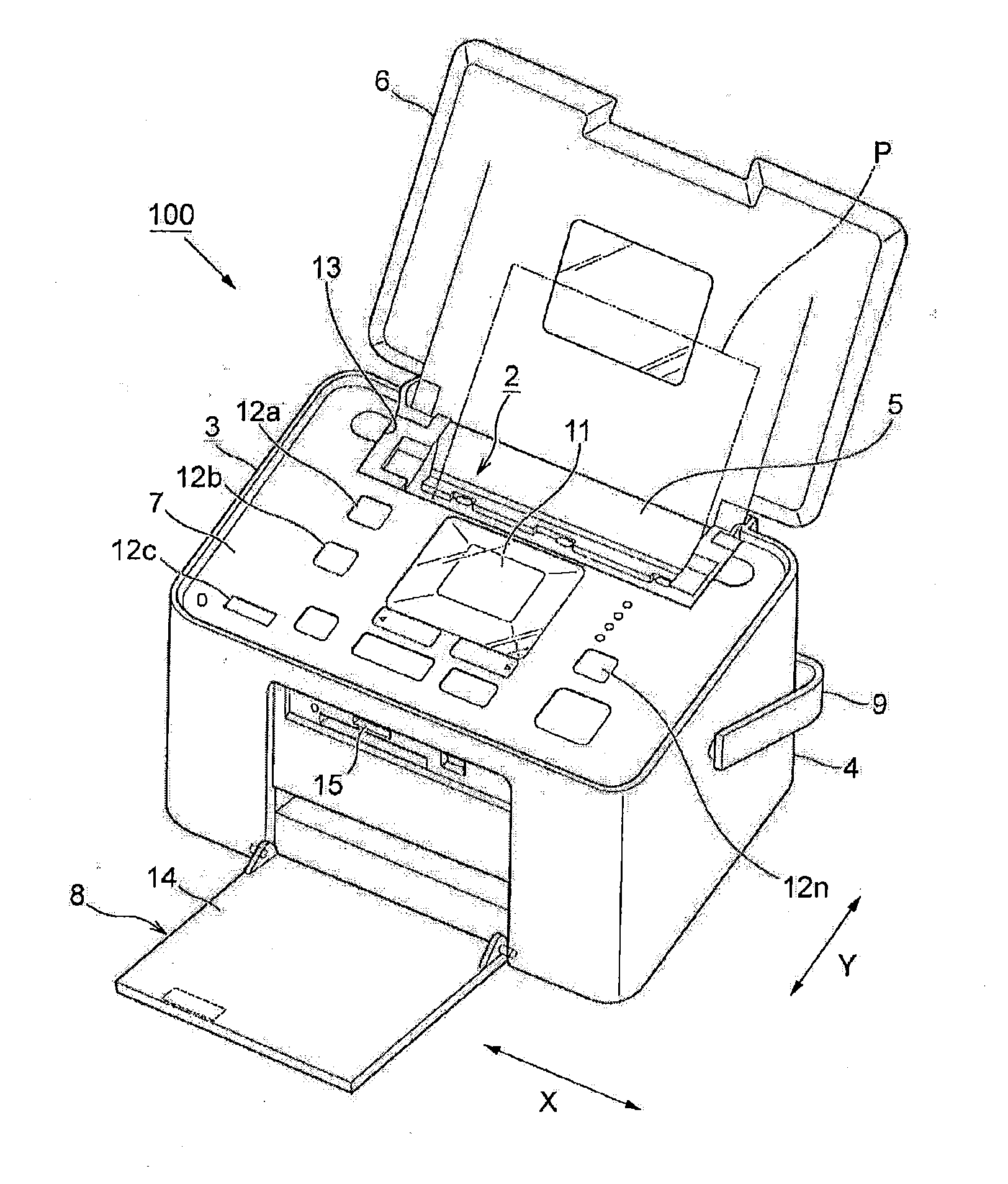
[0034] Hereinafter a shield plate fixing device and a recording apparatus of the liquid ejecting apparatus type equipped with the shield plate fixing device according to the present invention will be described. By way of example, an ink jet printer 100 is illustrated as a best mode for performing the liquid ejecting apparatus and the recording apparatus of the invention, and is used to schematically illustrate the whole construction based on the accompanying drawings.

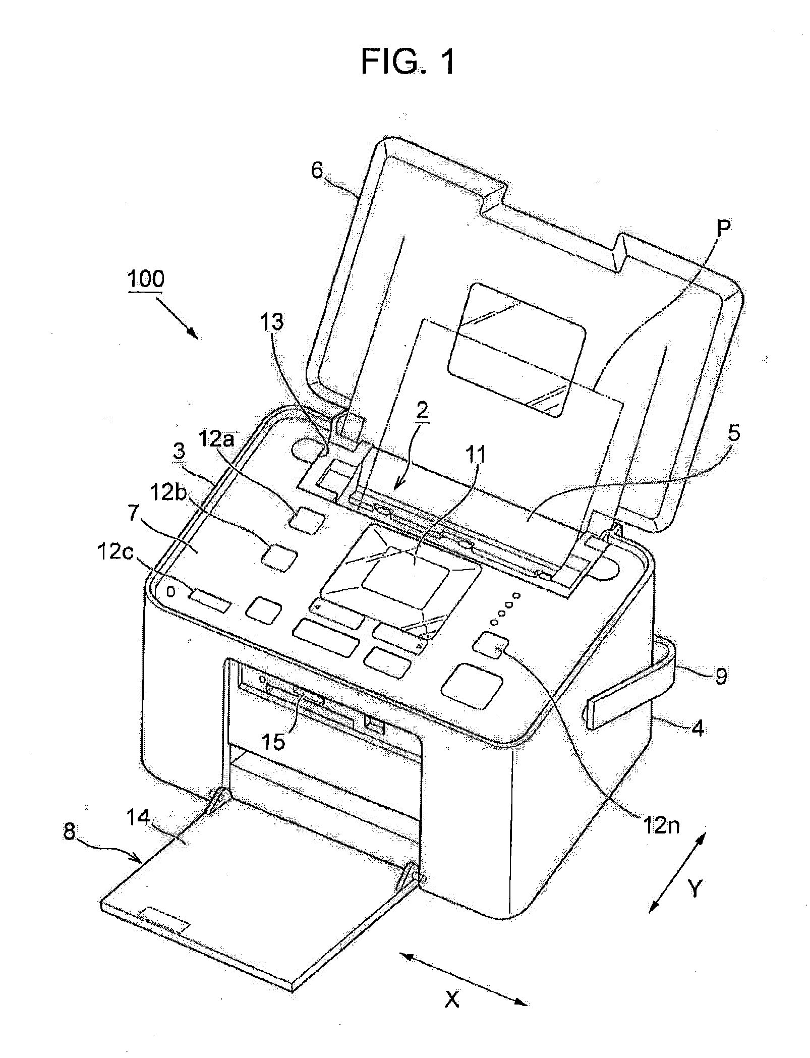
[0035]FIG. 1 is a perspective showing an ink jet printer from an oblique front direction when ready for use. FIG. 2 is a perspective view showing an appearance of the ink jet printer from an oblique front direction when being carried. FIG. 3 is a perspective view showing an appearance of the ink jet printer from an oblique rear direction during use.

[0036] Note that the ink jet printer 100 described here is an ink jet printer which is extremely compact and easy to carry, having a relatively simple structure directed to...


PUM


Abstract

A shield plate fixing device of an electronic apparatus includes a mechanical section for performing operation in a main body housing, an electronic substrate for controlling operation shielded by two upper and lower shield plates above the mechanical section, and an upper housing for sealing an upper opening of the main body housing above the electronic substrate. The mechanical section, the electronic substrate, and the upper housing are respectively placed in a stacked manner. The upper shield plate is directly fixed to the main body housing, so as to reduce tolerance accumulation in the assembled electronic apparatus.

Description

BACKGROUND [0001] 1. Technical Field [0002] The present invention relates to recording apparatuses and liquid ejecting apparatuses. More specifically, the present invention relates to shield plate fixing device that reduces tolerance accumulation in an assembled apparatus. [0003] 2. Related Art [0004] A conventional electronic apparatus, such as a recording apparatus or a liquid ejecting apparatus includes a main body housing designed to create the overall appearance of the electronic apparatus, a mechanical section for performing operation, an electronic substrate for controlling operation, and an upper housing for sealing an upper opening of the main body housing. Further, shield plates are provided above and below the electronic substrate to provide a shielding effect from the electromagnetic wave emitted from the electronic apparatus mounted on the electronic substrate. Each of the components constituting the electronic apparatus are arranged and combined in a stacked manner in ...

Claims


Application Information

Patent Timeline
IPC IPC(8): H01R13/648
CPCB41J29/02H01R13/65802H01R4/30H01R13/6582
Inventor MORIMOTO, MITSURUABE, MIKINOBU
Owner SEIKO EPSON CORP
Why Eureka
Try Eureka