
Method For Sparse Network Deployment Accuracy Enhancements

Inactive Publication Date: 2007-08-30
ANDREW LLC
View PDF40 Cites 54 Cited by
  • Summary
  • Abstract
  • Description
  • Claims
  • Application Information

AI Technical Summary

Problems solved by technology

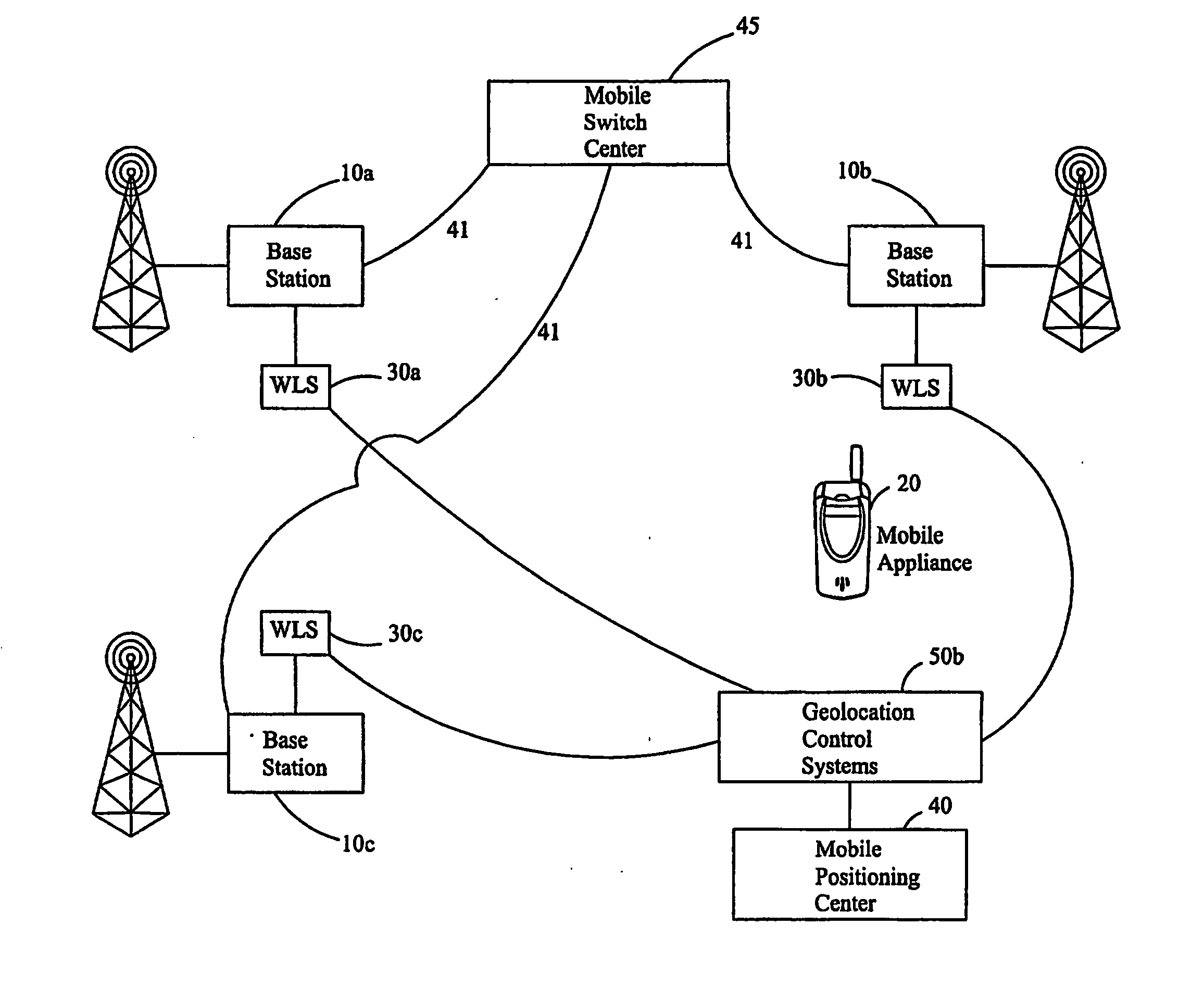
A specific problem in prior art methods is that a primary wireless location sensor must be located at the serving base station.
One effect of not having a WLS at every site is degradation of location accuracy.
For some air interfaces, this may be problematic.
For example, in AMPS and TDMA where the occupied bandwidth is small, the error associated with location estimates where the number of participating sites is reduced becomes unsatisfactory.
“No location areas“are those areas in which a minimum number of WLS cannot detect or measure an attribute of a signal such that the geo-location system cannot estimate a location.
However, if the base station that is serving the mobile appliance does not have WLS (due to the sparse deployment), then there is no WLS to “hear” the mobile at the serving site, and the neighboring site WLS units may not be able to hear the mobile because of severe power control resulting in low transmit power.

Method used


Image

  • Method For Sparse Network Deployment Accuracy Enhancements
  • Method For Sparse Network Deployment Accuracy Enhancements
  • Method For Sparse Network Deployment Accuracy Enhancements

Examples


Embodiment Construction

[0025] The present disclosure is directed towards methods to provide location related measurements in the “no location areas” as described above.

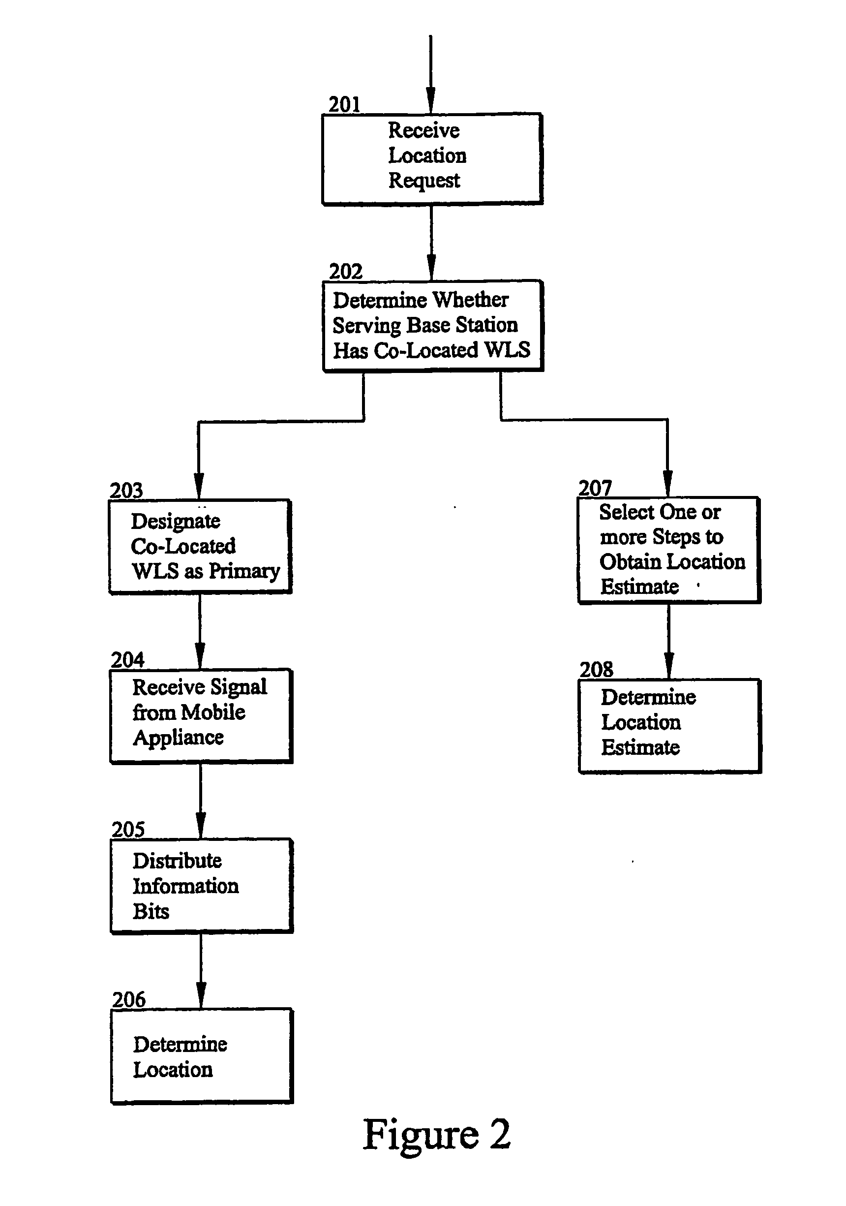
[0026] The disclosure presents various solutions that obviate the deficiencies in the prior art. The disclosure envisions all combinations and permutations of the following techniques in order to determine a location estimate. The disclosure also envisions use of the following described techniques individually or in combination conditioned on determining if a location hole exists,” no location” area, or not at all sites or some designated by different conditions. Conditions used as selection criteria include proximity, heard or not heard signal, signal quality, etc.

[0027] One location determining technique available for “no location” areas is the use of known data sequences (such as training sequence codes) in the transmission and having sites perform ambiguity function processing to detect a signal. This approach requires no data to be s...


PUM


Abstract

A method for use in a wireless communication system with a network overlay geolocation system having a sparse deployment network in which base stations of the wireless communication system may or may not have a co-located wireless location sensors (WLS). The method enables detection and measurement of a target mobile's signal independently from a primary WLS located at the base station serving the target mobile, which enable location estimated in previous “no location” areas. The method selects based on predetermined criteria from one or more of several techniques that aid in the detection and determining a location for the target mobile. The method selects from timing advance, power levels, pattern matching, EOTD, speed, and pseudo range measurements to estimate the location of the mobile. The method also uses ambiguity function processing to detect the signal and measure an attribute of the signal.

Description

CROSS REFERENCES [0001] The present application is related to and co-pending with and claims priority benefit of applications titled “A NETWORK OVERLAY GEO-LOCATION SYSTEM WITH SMART ANTENNAS AND METHOD OF OPERATION” SN#, “A SYSTEM AND METHOD FOR ENHANCING THE ACCURACY OF A LOCATION ESTIMATE” SN#, “NETWORK OVERLAY LOCATION SYSTEM AND METHOD FOR AIR INTERFACE WITH FREQUENCY HOPPING” SN#, “A SYSTEM AND METHOD FOR ESTIMATING THE MULTI-PATH DELAYS IN A SIGNAL USING A SPATIALLY BLIND ANTENNA ARRAY, SN#, And “WIRELESS COMMUNICATION NETWORK MEASUREMENT DATA COLLECTION USING INFRASTRUCTURE OVERLAY-BASED HANDSET LOCATION SYSTEMS” SN#, filed Oct. 16, 2003, the entirety of each of these applications is incorporated herein by reference. [0002] The present application is co-pending with and claims priority benefit of provisional application titled “System and method for enhancing location accuracy of mobile appliances in sparse network deployment” Ser. No. 60 / 480,735 filed Jun. 24, 2003, the ent...

Claims


Application Information

Patent Timeline
IPC IPC(8): H04Q7/20H04LH04W24/00H04W64/00
CPCG01S5/0252H04W64/00H04W24/00G01S5/06
Inventor KENNEDY, JOSEPH P. JR.CARLSON, PETERALLES, MARTIN
Owner ANDREW LLC
Learn More