Heat generating mechanism for hair dryer

US20070204477A1Inactive Publication Date: 2007-09-06LIN CHENG PING

Image

  • Heat generating mechanism for hair dryer
  • Heat generating mechanism for hair dryer
  • Heat generating mechanism for hair dryer

Examples


Embodiment Construction

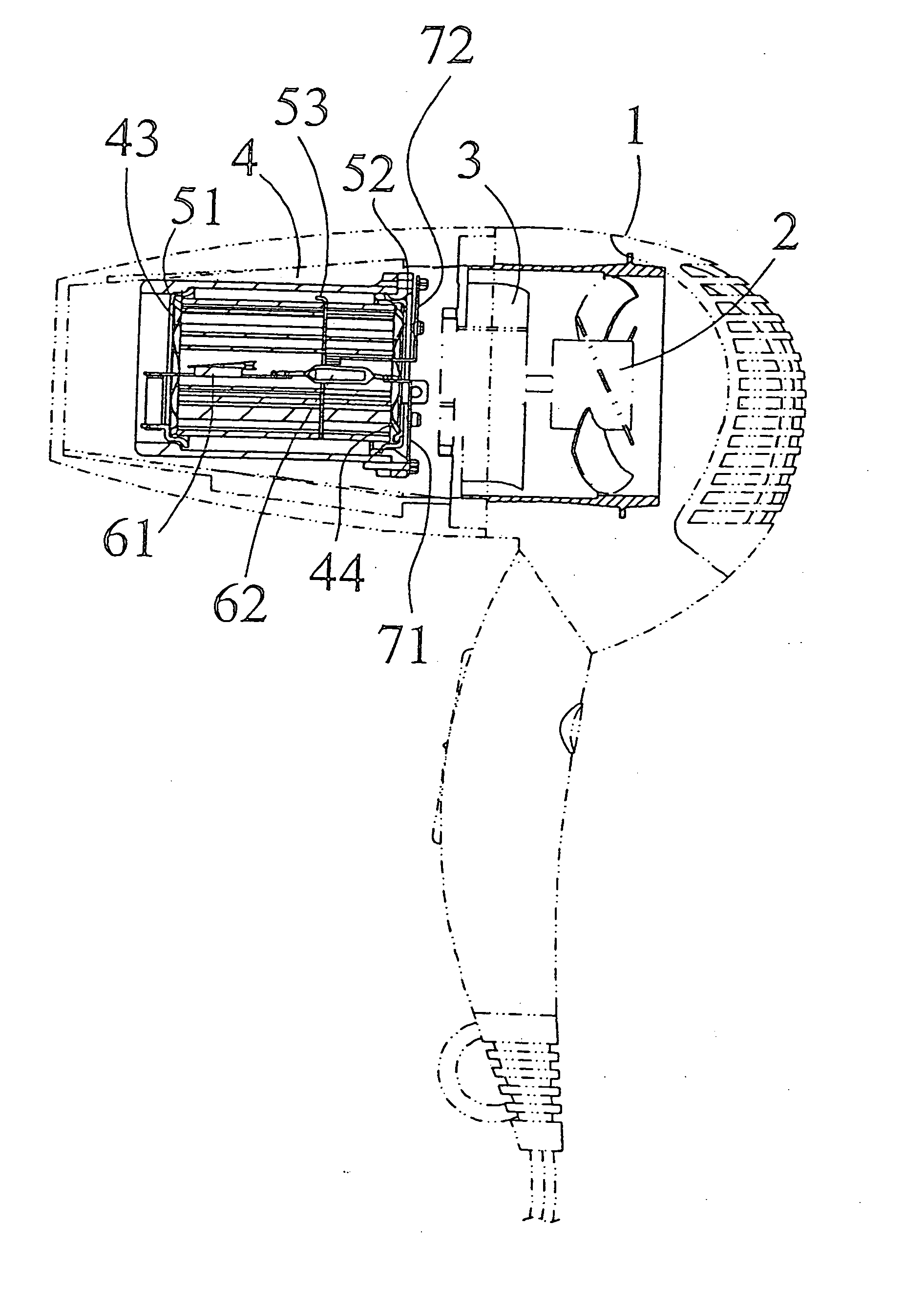
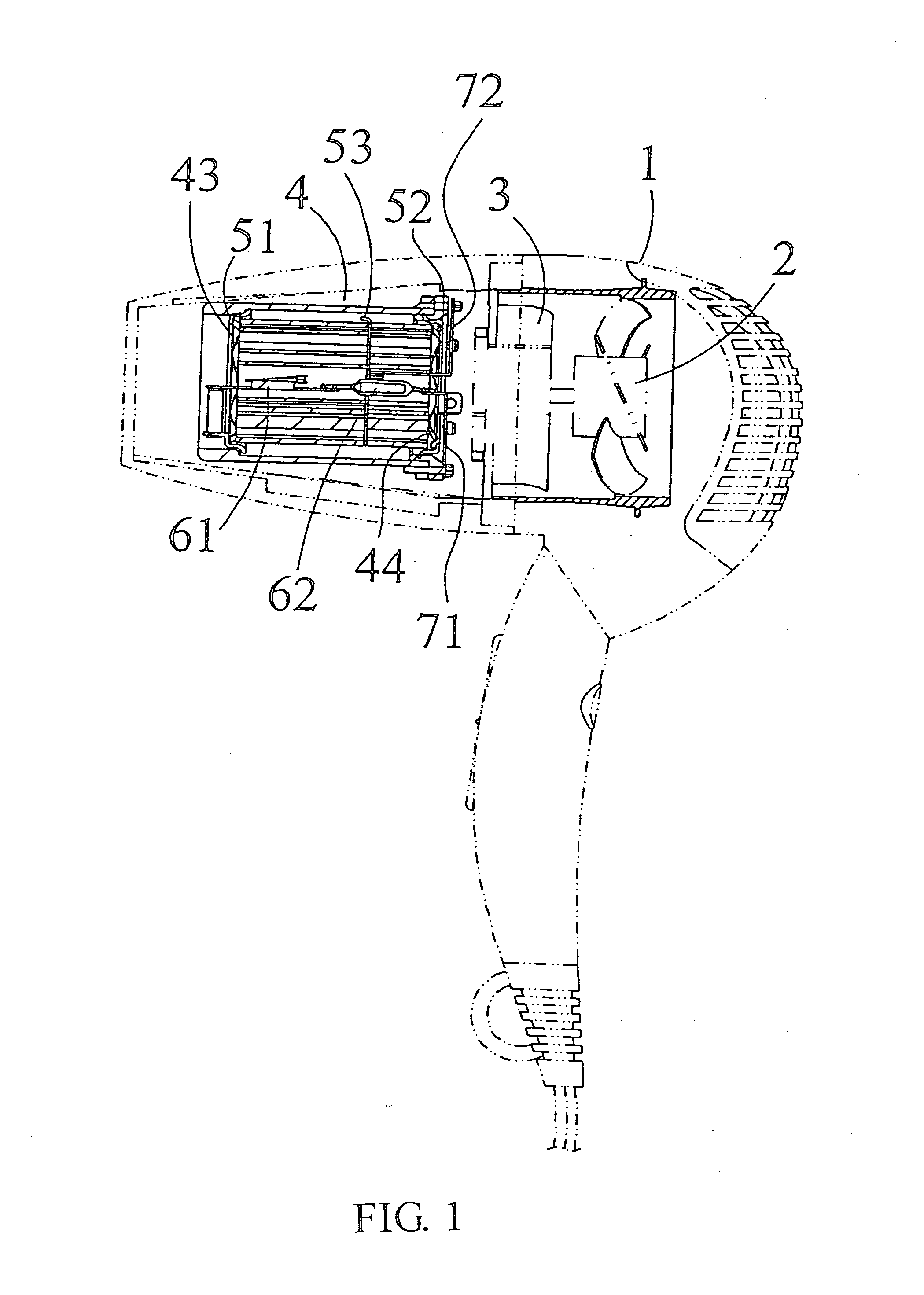
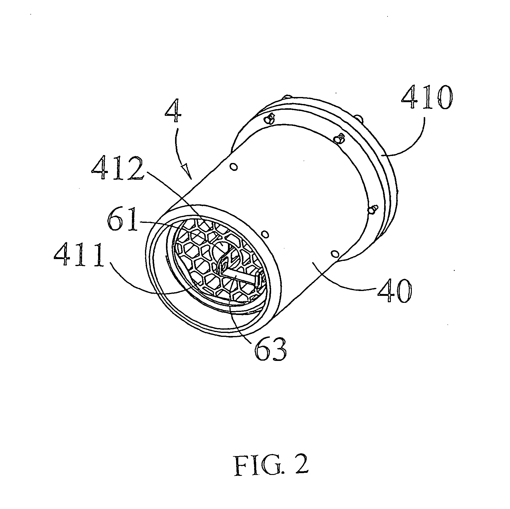
[0013] Referring to FIG. 1 through FIG. 4, the hair dryer according to the present invention has a housing 1 accommodating a fan 2, a motor 3, and a heat generating mechanism 4 in it. The heat generating mechanism 4 is composed of a first ceramic block 41, a second ceramic block 42, several electrically conducting reeds 43, 44 being attached to the two ceramic blocks 41, 42, and several heat shield rings 51, 52 attached to the aforesaid reeds, the whole structure is enclosed by an envelope 40.

[0014] Both the first and second ceramic blocks 41 and 42 are provided with a number of beehive like through pores 411, 421 . . . , and further have main passages 412 an 422 respectively formed axially at their center portions, and both passages 412, 422 are communicated with each other, an electrically conducting ring 53 is intercalated between the two ceramic blocks 41 and 42. The aforesaid electrically conducting reeds 43 and 44 are respectively attached to the outer ends of the ceramic blo...


PUM


Abstract

Disclosed is a heat generating mechanism for hair dryer having a housing in which accommodating a fan, a motor, and a heat generating mechanism which employs a ceramic block as a heat generating element, and an electrically conducting reed and a heat shield ring are respectively attached to both front and rear ends of the ceramic block. The ceramic block is a beehive figured porous body having a central main axial passage in which a temperature sensor switch is axially inserted.

Description

FIELD OF THE INVENTION [0001] The present invention relates to heat generating mechanism for hair dryer, and more particularly, to a beehive figured porous ceramic heat generating structure in which a temperature sensor switch is axially equipped along a central main passage of the ceramic block so as to detect the temperature in the ceramic block in the shortest time. DESCRIPTION OF THE PRIOR ART [0002] In the latest Taiwan local Utility Model Patent M263023, a new hair dryer is disclosed. The housing of the hair dryer is composed of two corresponding right and left sub-housings coupled together. The housing equipped with a wind outlet grids and a wind inlet net, contains an electric circuit control unit, a fan, a motor, a filter, and a motor voltage lowering unit in it. With the operation of the electric circuit control unit, the motor is rotated to drive the fan so as to introduce the air into the housing from the wind inlet and blow the air out of the housing via wind outlet gri...

Claims


Application Information

Patent Timeline
06 Sep 2007
Publication
US20070204477A1
IPC
A45D20/12; H05B6/12
CPC
A45D20/12; H05B2203/024; H05B3/10
Inventors
LIN, CHENG PING