Swing valve for a turbocharger with stacked valve members, and two-stage turbocharger system incorporating same

a turbocharger and valve member technology, applied in the field of turbochargers, can solve the problems of difficult modulation of flow control, single poppet not providing the ability to regulate, and the complexity of turbocharger systems for diesel engines in particular, and achieve the effect of facilitating compactness

Inactive Publication Date: 2007-09-06
HONEYWELL INT INC
View PDF23 Cites 33 Cited by
  • Summary
  • Abstract
  • Description
  • Claims
  • Application Information

AI Technical Summary

Benefits of technology

[0005] The present invention addresses the above needs and enables other advantages by providing a swing valve having “stacked” valve members or poppets. The swing valve has a compact configuration by virtue of the stacked valve members. The compactness is further facilitated in particular embodiments by an actuating mechanism having actuating shafts that rotate about the same axis and are both driven by a single actuator. However, in other embodiments, multiple actuators can be employed for separately actuating the valve members.
[0013] Alternatively, the secondary valve member itself can include a component that dampens and reduces the vibration of the valve member.

Problems solved by technology

Turbocharger systems for diesel engines in particular are becoming more and more complex because of the increasing performance demands from such engines.
A simple swing valve having a single poppet does not provide the ability to regulate the flow through the valve, since the valve is either open or closed.
In addition, the flow area increases rapidly with a single swing valve as the valve begins to open, making the flow control difficult to modulate.
However, the combination of two swing valves each with its own actuator presents and large and awkward assembly that is difficult to package in the vehicle system where space is often at a premium.

Method used


Image

  • Swing valve for a turbocharger with stacked valve members, and two-stage turbocharger system incorporating same
  • Swing valve for a turbocharger with stacked valve members, and two-stage turbocharger system incorporating same
  • Swing valve for a turbocharger with stacked valve members, and two-stage turbocharger system incorporating same

Examples


second embodiment

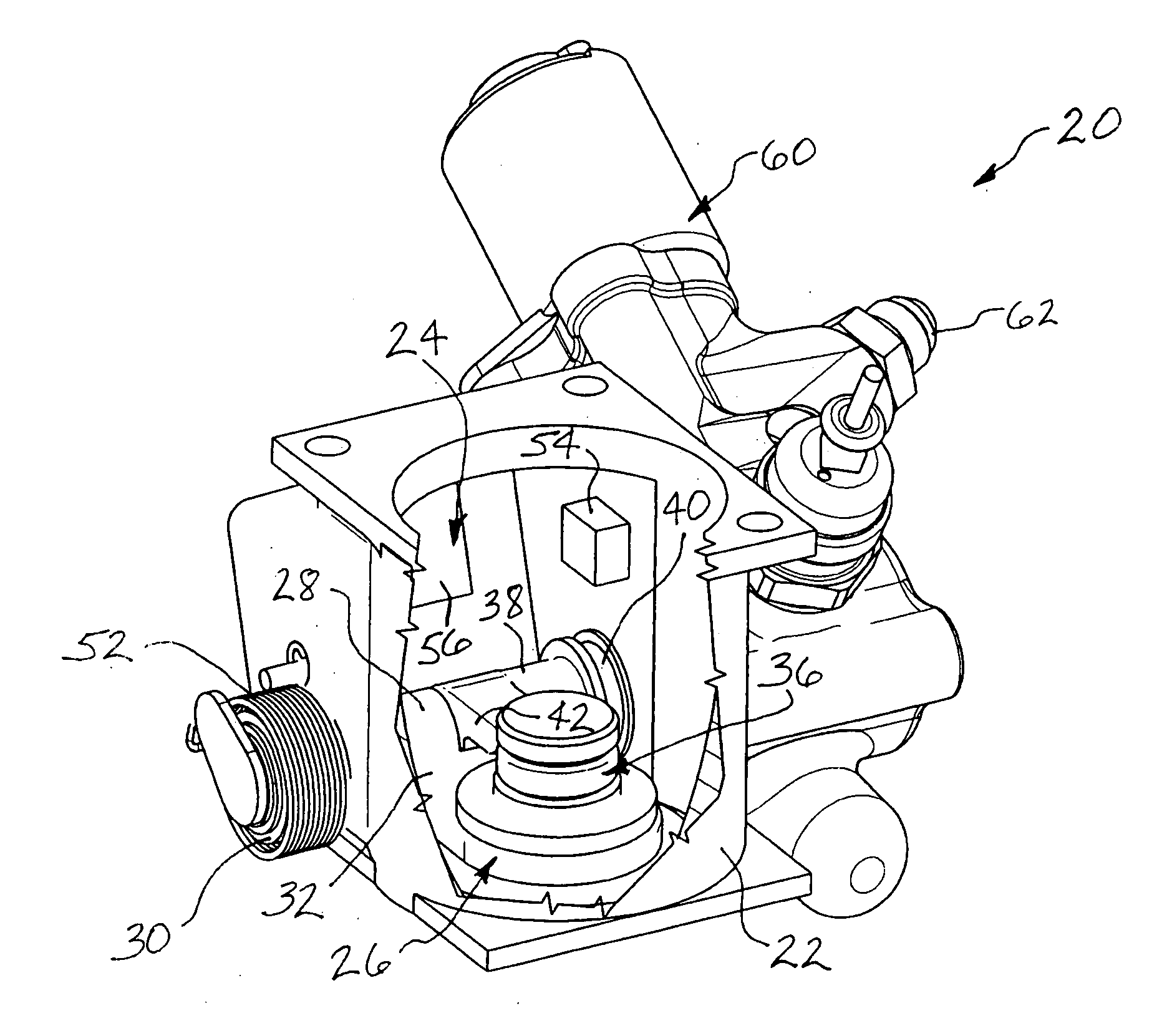
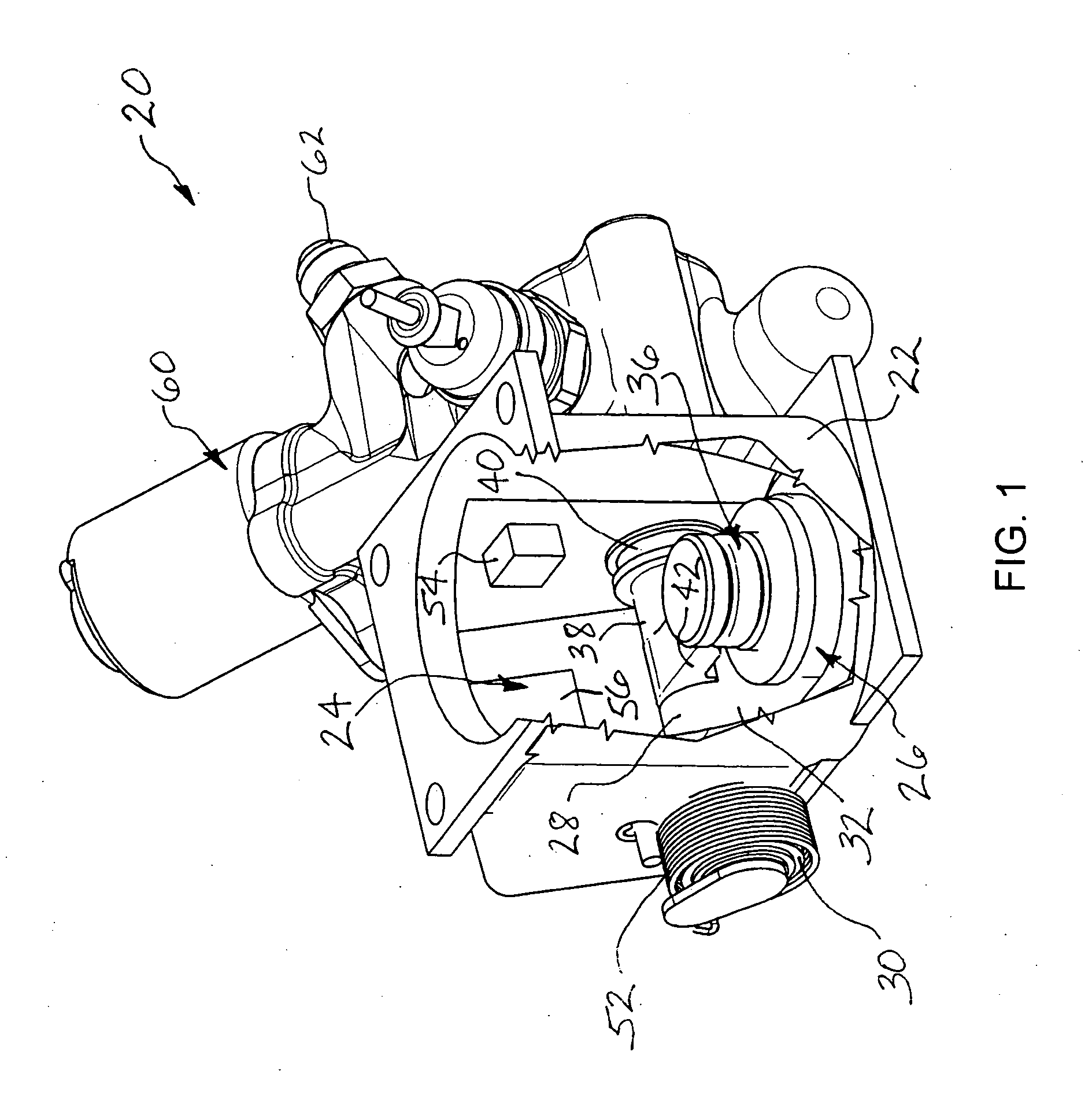
[0031] The primary valve member 26 pivots between a closed position (FIGS. 1, 5, and 6) in which the primary valve member blocks the primary valve passage 24 (except that, as further described below, a relatively small amount of flow can occur via the secondary valve passage and valve member), and an open position (FIGS. 3, 4, and 7) in which the primary valve member does not present any significant obstacle to the flow of gas through the primary valve passage. In the closed position, the primary valve member 26 engages a primary valve seat (not shown in this embodiment, but illustrated in FIGS. 9-12) to seal the primary valve member so that flow is substantially prevented from flowing between the primary valve member and the seat. The primary valve seat either can be disposed within the valve housing 22 (e.g., integrally formed in the valve housing, or separately formed and then installed in the valve housing), or alternatively can be part of another component (not shown) that is a...

first embodiment

[0042] A swing valve 120 in accordance with another embodiment of the invention is illustrated (without any actuator) in FIGS. 9-13. The valve includes a valve housing 122 defining a primary valve passage 124, a primary valve member 126 affixed to a primary shaft 128, and a secondary valve member 136 affixed to a secondary shaft 138. The valve housing 122 defines a primary valve seat 123 that the primary valve member 126 engages in its closed position as shown in FIGS. 11 and 12. This is the primary difference relative to the first valve 20, in which the primary valve seat is provided in another component coupled with the valve 20. In other respects, the valve 120 is generally similar to the first embodiment above.

[0043] The secondary valve member 136 engages a secondary valve seat 150 formed on the primary valve member 126 in the closed position (FIG. 11). In this condition, the valve 120 is fully closed. Partial opening is achieved by rotating the secondary shaft 138 to open the s...


PUM


Abstract

A swing valve has a pivoting primary valve member for closing a primary valve passage defined in a valve housing, and a pivoting secondary valve member for closing a secondary valve passage defined through the primary valve member. Partial opening of the valve is achieved by pivoting the secondary valve member open while the primary valve member remains closed. Full opening of the valve is achieved by rotating the primary valve member open.

Description

BACKGROUND OF THE INVENTION [0001] The invention relates to turbochargers in general, and more particularly relates to waste gate or bypass valves for turbocharger systems. [0002] Turbocharger systems are employed for boosting the performance of internal-combustion engines such as gasoline and diesel engines used for passenger automobiles, trucks, marine craft, aircraft, and various other types of vehicles. Turbocharger systems for diesel engines in particular are becoming more and more complex because of the increasing performance demands from such engines. For example, it is becoming increasingly common to employ multiple-turbocharger systems such as serial sequential turbochargers and the like in order to meet the stringent performance requirements. [0003] In such turbocharger systems, there is frequently a need to divert or bypass a flow of gas (whether air on the compressor side of the system, or exhaust gas on the turbine side of the system). For example, in a series turbochar...

Claims


Application Information

Patent Timeline
Patent Type & Authority Applications(United States)
IPC IPC(8): F02D23/00F02B33/44
CPCF02B37/013F02B37/127Y02T10/144F02B37/18F02B37/183F02B37/16F02B37/162Y02T10/12
Inventor MARTIN, STEVEN P.MCGRAW, ANDREW F.
Owner HONEYWELL INT INC
Why Eureka
Try Eureka