

Oxidant-swirled fossil fuel injector for a shaft furnace
a shaft furnace and injector technology, applied in furnaces, combustion types, manufacturing converters, etc., can solve the problems of carbon soot formation, limiting pulverized coal utilization, and irregular charge reduction and charge reduction
- Summary
- Abstract
- Description
- Claims
- Application Information
AI Technical Summary
Benefits of technology
Problems solved by technology
Method used
Image

Examples
example 1
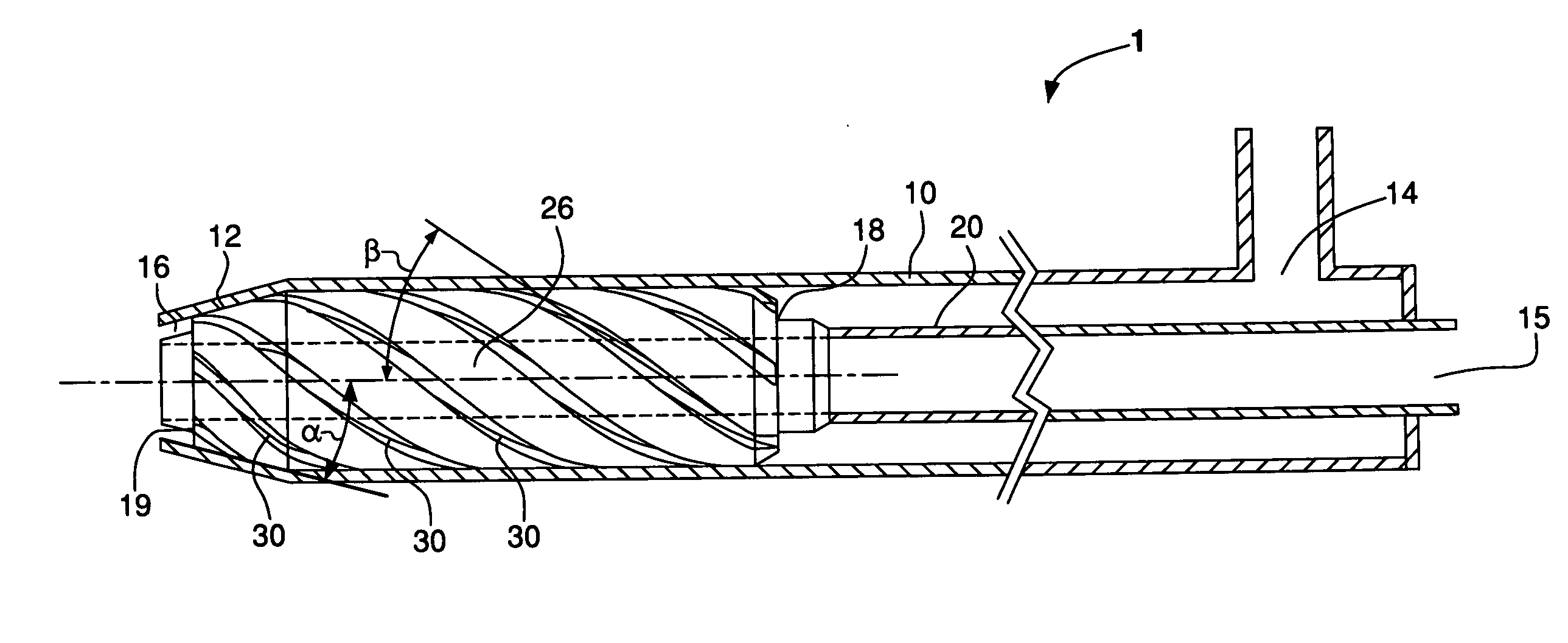
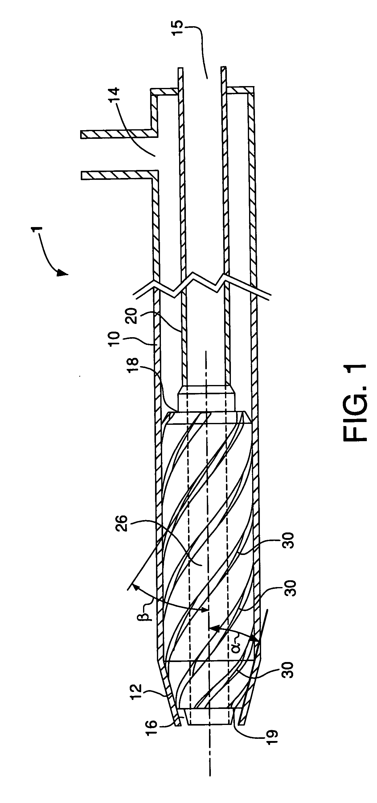
[0042] An injector according to the present invention was constructed and tested. The injector comprised an inner conduit having a generally circular cross-section for conveying fossil fuel and an outer conduit, also having a generally circular cross-section, surrounding the inner conduit, which formed an annulus for conveying and swirling oxidant. The inner diameter of the inner conduit was about 8.687 mm. The outer diameter of the outer conduit was about 48.26 mm and the inner diameter of the outer conduit was about 29.49 mm. The inner surface of the outer conduit terminated in a converging inner surface having an angle of about 15° relative to the longitudinal axis.
[0043] The means for swirling the oxidant comprised six evenly-spaced spiral-like passages (grooves) machined into the outer surface of the inner conduit and had a rotation of about 180°. The spiral-like passages were generally rectangular, having width and height dimensions of about 2.5 mm by 2.5 mm. The swirl angle ...
example 2
[0050] A second injector according to the present invention was constructed and tested. This second injector was similar to the injector described in Example 1 with the exception that the cross-section of the spiral-like passages, which had a width of about 2.5 mm and a height of about 1.25 mm. The cross-sectional area of the spiral-like passages was therefore halved, resulting in a higher flow velocity for the same flow rate compared to the injector in Example 1.
[0051] Table 2 summarizes process conditions and LOI results for the injector having higher oxidant swirl velocity. The LOI data shows that the samples corresponding to operating conditions with swirl oxidant have a lower percentage loss on ignition, indicating less carbon soot produced for the injector according to the present invention. Exhaust O2 concentrations were not measured for Samples 6-1 and 6-2.
TABLE 2Swirl O2 flowCoal flow raterateExhaust O2LOISample #(kg / h)(Nm3 / h)(vol %)(%)6-125059—36.096-22200—49.29
PUM
| Property | Measurement | Unit |
|---|---|---|
| rotation | aaaaa | aaaaa |
| rotation | aaaaa | aaaaa |
| swirl angle | aaaaa | aaaaa |
Abstract
Description
Claims
Application Information