Trailer hitch

a trailer and hitch technology, applied in the field of trailer hitch assembly, can solve the problems of requiring skill and/or multiple attempts to properly align, damage to the vehicle and trailer, and difficulty in adjusting the traverse of the trailer, so as to reduce the friction coefficient and the effect of lowering the friction coefficien

Inactive Publication Date: 2007-09-06
HAMILTON MARINE
View PDF8 Cites 31 Cited by
  • Summary
  • Abstract
  • Description
  • Claims
  • Application Information

AI Technical Summary

Benefits of technology

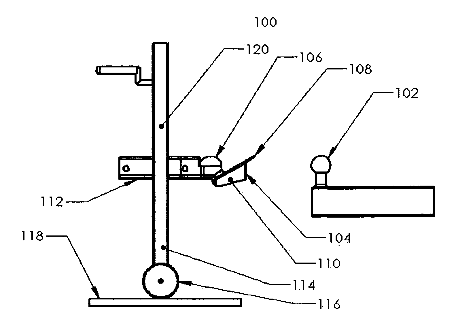
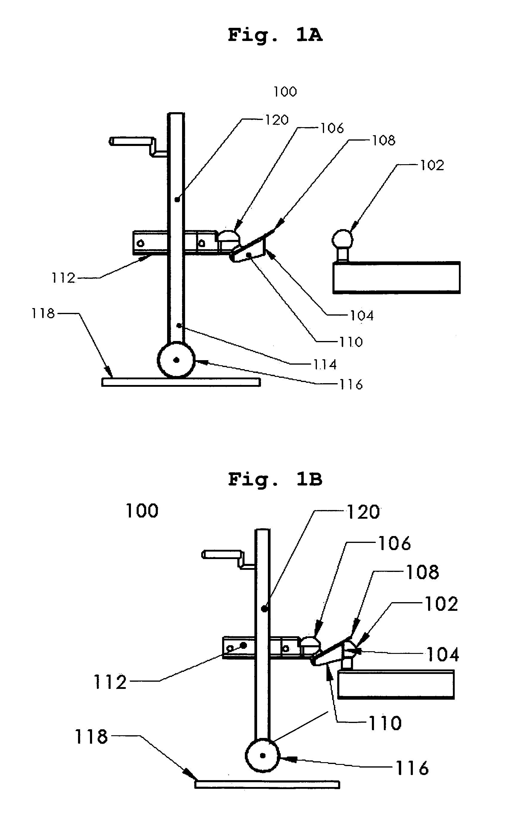
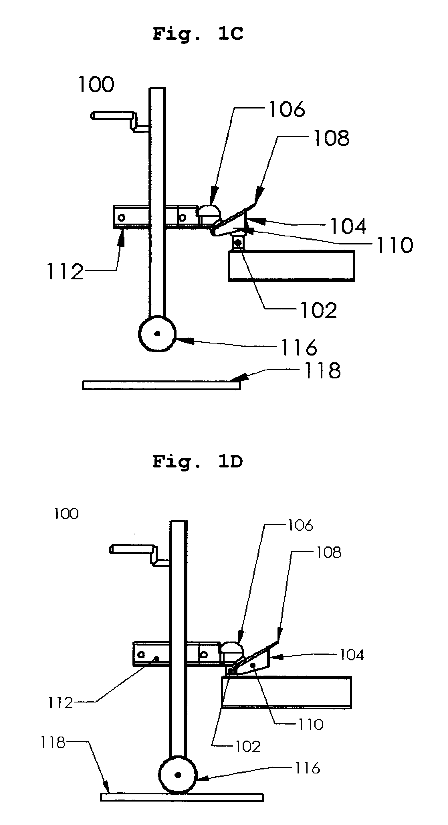
[0007] Alternate embodiments may include one or more of the following. The two side plates may extend at a downward angle from each side edge of the receiver plate between the proximal end and distal end with the bottom edge of the plates being substantially parallel with the ground. In this embodiment, the side plates are designed to interfere and make contact with the hitch ball support member when the tow vehicle is making a sharp turn. This calculated interference is designed to prevent a common problem commonly known as “jack-knifing” of the trailer. The proximal end of the receiver plate may have a rounded profile. The receiver plate may have an offset lip extending parallel with the downward angle of the receiver plate that creates a pocket for the front flange of the hitch socket. The receiver plate ball contact surface and the inner surfaces of the two side plates may have an applied coating to obtain wear resistance and to lower the coefficient of friction. Similarly, the hitch ball socket may have a friction reducing coating applied to its inner surface. Alternately, the receiver plate may have a wear plate coupled its ball contact surface area to protect the hitch ball and the receiver plate from excessive wear or damage and to lower the coefficient of friction between the hitch ball and the receiving plate. The wear plate may have an offset lip extending parallel with the downward angle of the receiver plate that creates a pocket for the front flange of the hitch socket. The receiver plate may be formed with a proximity indicator which may consist of a thin bump or series of bumps or valleys formed into the ball contact surface of the receiver plate, offset proximally a small distance from the front radius of the hitch socket. Alternately, if a wear plate is used, the wear plate may be formed with a proximity indicator, which may consist of a thin bump or series of bumps or valleys formed onto the ball contact surface of the wear plate, offset proximally a small distance from the front radius of the hitch socket. An exemplary embodiment, according to the present invention, provides a trailer hitch metal body that is a one piece construction. The one piece construction trailer hitch unit, usually a stamped or cast metal body, includes the trailer frame tongue attachment portion, the ball socket portion and the angled receiver plate with two side plates. The one piece embodiment may include all of the features of the above add-on embodiment. Additionally, in this embodiment, the ball socket circumference may be manufactured at a downward sloping angle, in the proximal to distal direction. In this embodiment the highest point of the socket lip is the proximal or leading edge of the socket and the lowest point on the lip is the distal or trailing edge of the socket. In other words, the front lip of the socket is higher than all other edges of the socket portion. The socket portion may have a self-latching device.
[0008] It is important to note that the present invention is not intended to be limited to a system or method which must satisfy one or more of any stated objects or features of the invention. It is also important to note that the present invention is not limited to the exemplary embodiments described herein. Modifications and substitutions by one of ordinary skill in the art are considered to be within the scope of the present invention, which is not to be limited except by the claims stated later herein.

Problems solved by technology

Aligning the ball portion underneath the socket portion often requires skill and / or multiple attempts to properly align the ball portion underneath the socket.
Damage to the vehicle and trailer may result if the user backs the vehicle up too far and drives the vehicle into the hitch portion, or into a portion of the trailer.
If the trailer is located in sand or soft or uneven ground, the wheel at the base of the supporting front trailer jack, if so equipped, will not allow for traverse adjustment of the trailer, requiring exact alignment of the towing vehicle ball with the trailer socket.
Lack of an assistant to guide the user, inclement weather, and lack of lighting may further complicate the hitching process.
However, these devices are limited in the scope of their usefulness.
The guiding mechanisms may not handle the full tongue weight of the trailer.
They do not account for a trailer jack without a wheel or a trailer jack that is positioned in sand, soft or uneven ground, rendering them ineffective in these conditions.
Other systems are not designed to elevate the front of the trailer off of the ground at its support point for full, unencumbered side to side traverse alignment as the towing vehicle is backing.
Current systems may cause excessive wear of the hitch ball and guiding mechanism over time due to metal-to-metal contact friction with repeated coupling.
Current guiding mechanisms also do not alert the user when the socket portion is about to receive the ball.

Method used


Image

  • Trailer hitch
  • Trailer hitch
  • Trailer hitch

Examples


first embodiment

[0038] The “U” shaped channels 304 may also be coupled to the frame or socket portion with fasteners 310. The fasteners 310 may include, for example, but not limited to bolts, screws, rivets, welds, or adhesives. The fasteners 310 may permanently couple the guide assembly 300 to the trailer or, for example, may utilize bolts with wing nuts to allow the user the ability to remove the guide assembly 300 as needed. Referring to FIG. 3A and 3B, the receiver portion 308 may have a lip portion 314. The lip portion 314 may be located between the receiving plate 308 and the opening of the socket. The lip portion 314 provides a recess for the front flange of the trailer hitch assembly in the The side plates 312 may extend down and run parallel with the receiver plate 308 to prevent any interference during towing as shown in FIG. 3B. This allows the side plates 312 to ride above the towing portion as shown in FIG. 3E. The side plates 312 may also extend downward and specifically be designed ...

third embodiment

[0043] According to this invention, the lip portion 314, referring to FIGS. 3A-D, may provide a pocket for the front flange of the hitch socket. This pocket feature may be on the ball contact surface of the receiver plate 308 as in FIG. 3D or may be a feature cut into the wear plate 908 as in FIG. 6B. The pocket allows an area for the hitch flange 910 to slip into for a smooth transition of the ball into the socket without hitting or catching on the bump that would be otherwise be encountered by the leading edge of the socket flange 910. This feature may prevent excessive resistance to the coupling process or wear or damage to the hitch flange. Referring to FIG. 6B, this pocket feature 906 may also be formed or cut into the wear plate 908 to create a smooth transition as the hitch ball travels towards and into the hitch socket 608 without hitting or catching on a bump that would otherwise be created by the leading edge of the hitch flange 910.

[0044] According to FIG. 6A, FIG. 6B, FI...


PUM


Abstract

A system, method, and device for hitching a trailer to a vehicle are disclosed. The exemplary system may have a receiving plate with a distal end formed with or coupled to the socket portion. The receiving plate may extend to a proximal end from the socket at an incline. The proximal end may be wider than the distal end. Two support members may extend substantially beyond a socket portion. Two side plates may extend at a downward angle from each side edge of the receiving plate between the proximal end and proximal end. The two side plates may extend downwards to interfere with sharp angled turning.

Description

TECHNICAL FIELD [0001] The present invention relates to a trailer hitch assembly and more particularly, relates to a self-guiding trailer hitch. BACKGROUND INFORMATION [0002] Trailers pulled by a vehicle are often coupled via a ball and socket type hitch. The vehicle has a ball portion that extends vertically from the frame of the hitch. The frame of the hitch may be coupled to the frame or other structural point on the vehicle. The ball portion is designed to receive a socket that fits over the top of the ball portion. The ball portion may range in size from about 1 to 3 inches in diameter. The socket portion is coupled to the frame or structural point on the trailer and faces in a downward direction. The socket portion fits over the ball portion when the trailer is coupled to the vehicle. The socket typically has a latching device that narrows the throat of the socket and prevents the socket from lifting off of the ball portion during use of the hitch. Additional chains may be use...

Claims


Application Information

Patent Timeline
Patent Type & Authority Applications(United States)
IPC IPC(8): B60D1/36
CPCB60D1/66B60D1/363
Inventor HAMILTON, BRUCENARDI, STEVEN
Owner HAMILTON MARINE
Why Eureka
Try Eureka