Rotor Of Rotating Electric Machine
a technology of rotating electric machines and rotating plates, which is applied in the direction of rotating magnets, synchronous machines with stationary armatures, magnetic circuit rotating parts, etc., can solve the problems of heavy burden on the core portion, excessive stress on thinned magnetic steel plate b, /b>, etc., to prevent fatigue breakdown of the magnetic steel plate, suppress the adhesion between the end plate and the magnetic steel plate with the adhesive
- Summary
- Abstract
- Description
- Claims
- Application Information
AI Technical Summary
Benefits of technology
Problems solved by technology
Method used
Image

Examples
first embodiment
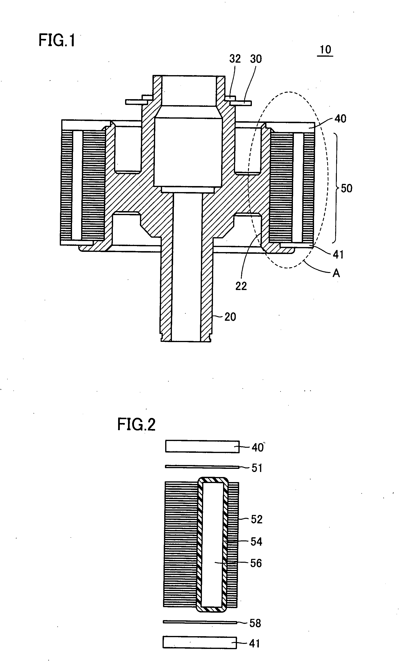
[0043]FIG. 1 is a cross sectional view of a rotor of a rotating electric machine in the present embodiment.
[0044] Referring to FIG. 1, a rotor 10 includes a shaft 20, a rotor core 50 held around shaft 20, end plates 40 and 41 sandwiching rotor core 50, a resolver 30 detecting rotation of rotor 10, and a snap ring 32 securing resolver 30 to prevent it from being pulled out.
[0045] Around shaft 20 is formed a flange 22 for holding rotor core 50 having stacked magnetic steel plates.
[0046]FIG. 2 is a view for illustrating a portion A in FIG. 1 in detail.
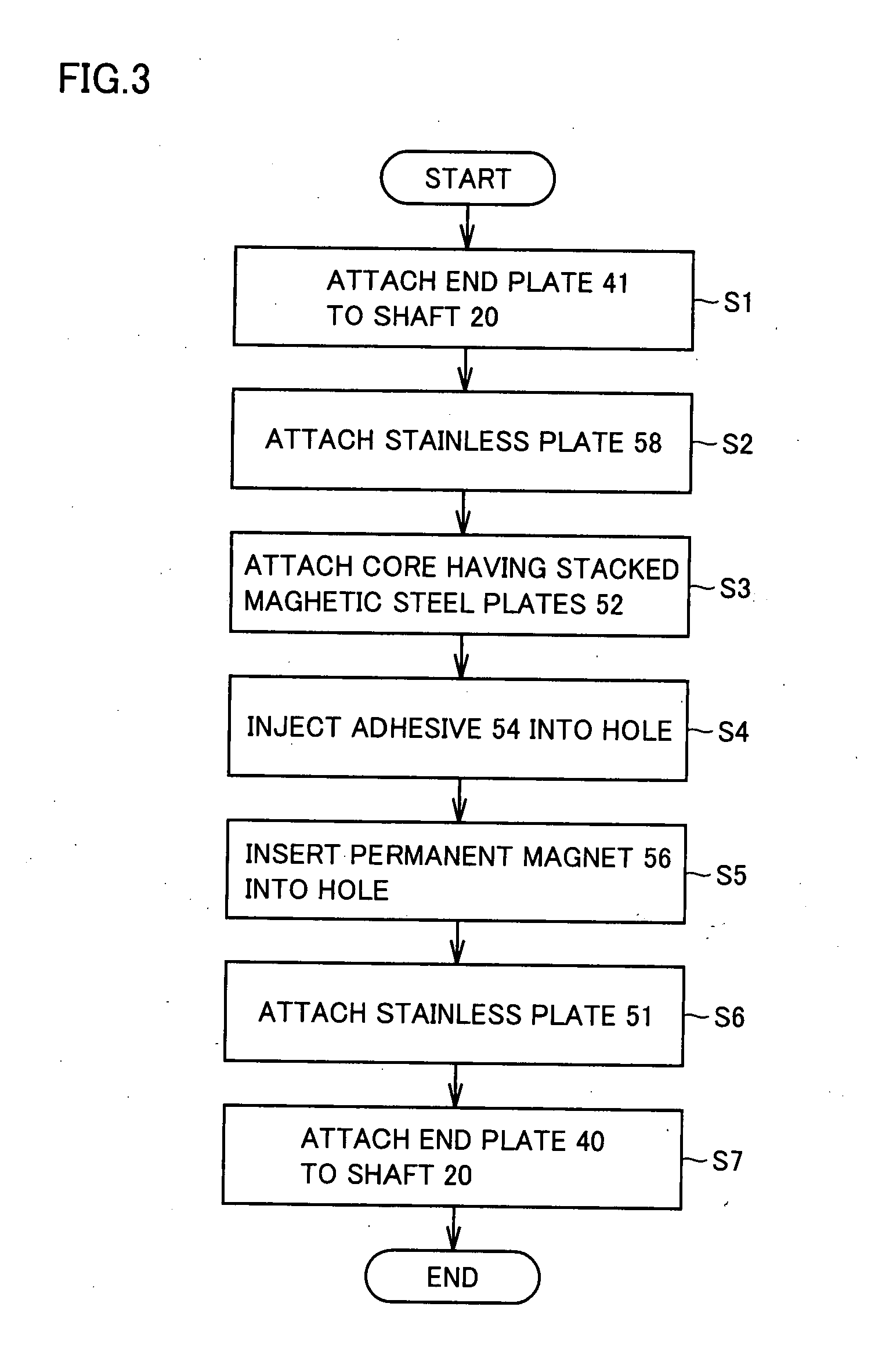
[0047]FIG. 3 is a flow chart for illustrating a process of assembling the rotor.
[0048] Referring to FIGS. 2 and 3, firstly in step S1, end plate 41 is attached to shaft 20 in FIG. 1. Next, in step S2, a stainless plate 58 is attached over the end plate. Further, in step S3, the rotor core having stacked magnetic steel plates 52 is attached to overlie stainless plate 58.
[0049] As a result of stacking magnetic steel plates 52, holes 1...
second embodiment
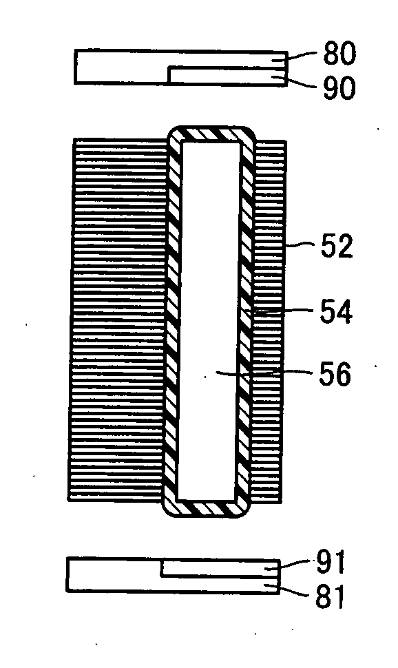
[0067]FIG. 6 is a view for illustrating a rotor in a second embodiment.
[0068] Referring to FIG. 6, the rotor in the second embodiment includes an end plate formed of a main member 80 and a sub-member 90, and an end plate formed of a main member 81 and a sub-member 90, instead of end plates 40 and 41 and stainless plates 51 and 58 of the rotor in the first embodiment illustrated in FIG. 2.
[0069] Non-magnetic sub-member 90 is fitted into main member 80. Similarly, non-magnetic sub-member 91 is fitted into main member 81. Main members 80 and 81 are preferably made of a lightweight and nonmagnetic aluminum alloy, as end plates 40 and 41 in the first embodiment. Further, sub-members 90 and 91 are made of a non-magnetic material having a linear expansion coefficient close to that of magnetic steel plate 52. For example, sub-members 90 and 91 can be made of a stainless steel.
[0070]FIG. 7 is an enlarged view showing a portion of the end plate in FIG. 6.
[0071] In FIG. 7, sub-member 90 is...
third embodiment
[0077]FIG. 9 is a view for illustrating a rotor in a third embodiment.
[0078] Referring to FIG. 9, in the third embodiment, a mold release agent is applied beforehand to end plates 40 and 41 on the sides in contact with the magnetic steel plates, to provide layers 70 and 71 of the mold release agent. These layers 70 and 71 of the mold release agent serve as adhesion suppressing portions suppressing adhesion force of the adhesive to end plates 40 and 41.
[0079] Concrete examples of the mold release agent include a silicon-based coating agent, a fluorine-based coating agent (Teflon (registered trademark) coat), and the like.
[0080] Thereby, adhesion between magnetic steel plates 52 and end plates 40 and 41 with adhesive 54 is prevented, and thus stress imposed on magnetic steel plates 52 can be reduced even when end plates 40 and 41 expand and shrink during a thermal cycle.
PUM
| Property | Measurement | Unit |
|---|---|---|
| adhesion | aaaaa | aaaaa |
| elastic | aaaaa | aaaaa |
| non-magnetic | aaaaa | aaaaa |
Abstract
Description
Claims
Application Information
 - R&D Engineer
- R&D Manager
- IP Professional
- Industry Leading Data Capabilities
- Powerful AI technology
- Patent DNA Extraction
Browse by: Latest US Patents, China's latest patents, Technical Efficacy Thesaurus, Application Domain, Technology Topic.
© 2024 PatSnap. All rights reserved.Legal|Privacy policy|Modern Slavery Act Transparency Statement|Sitemap