Wireless bike brake light

a brake light and wireless technology, applied in the direction of anti-theft devices, cycle equipments, anti-theft cycle devices, etc., can solve the problem of only responsive brake lights, and achieve the effect of low natural mechanical friction and low friction

Inactive Publication Date: 2007-09-06
LU YEN HO
View PDF5 Cites 12 Cited by
  • Summary
  • Abstract
  • Description
  • Claims
  • Application Information

AI Technical Summary

Benefits of technology

[0004]The main features of this invention are the employment of a MEMS-structured accelerometer chip, and controlling techniques, which enable the invention to give off brake light when encountering mechanical frictions—mainly by braking, even if the braking is light. It is so because (1) the applied vehicle is a bike, which has special character, and (2) the control circuits unit of this invention also detects stop / moving status of the bike besides deceleration. A bike has different characters (very low natural mechanical frictions) from cars or motorcycles. When a bike accelerates on downhill road naturally without pedaling, theoretically the accelerometer will output the same signal magnitude as that when a bike is slowing down gradually naturally without pedaling on the plain road, or when a bike is slowing down rapidly naturally without pedaling on uphill road. This is so because when a bike accelerates on downhill road naturally without pedaling, the acceleration effect will be mostly offset by gravity due to its “low friction” character. On the contrary, when a bike decelerates on uphill road naturally without pedaling, the deceleration effect will also be offset by gravity.

Problems solved by technology

The only problem happens when a bike stops on a steep downhill road because the accelerometer will sense G-force only, which makes the brake light mistakenly light up given that the bike is NOT actually in motion, and also NOT in deceleration condition.
So, when the control circuits unit detects that the bike is not moving, it will NOT command the lighting device to give off brake light even if a deceleration signal is also detected by the accelerometer (because it could be caused by G-force, not really by deceleration force), making brake light only responsive when bikes in motion encounter noticeable mechanical frictions mainly by braking.

Method used


Image

  • Wireless bike brake light
  • Wireless bike brake light
  • Wireless bike brake light

Examples


Embodiment Construction

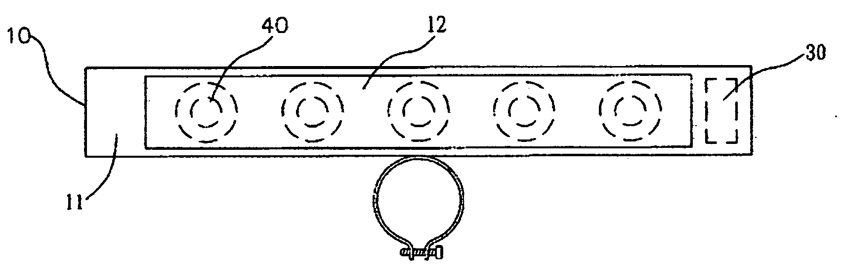
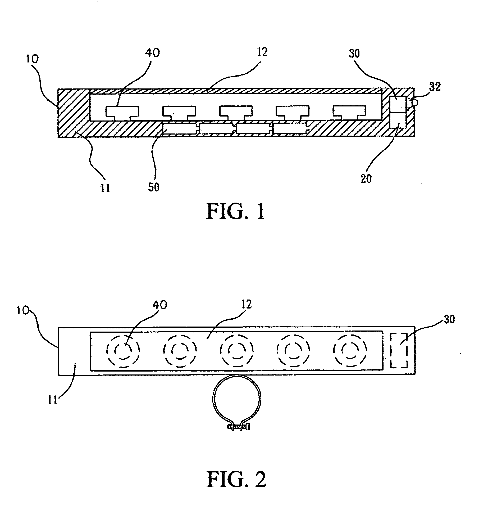
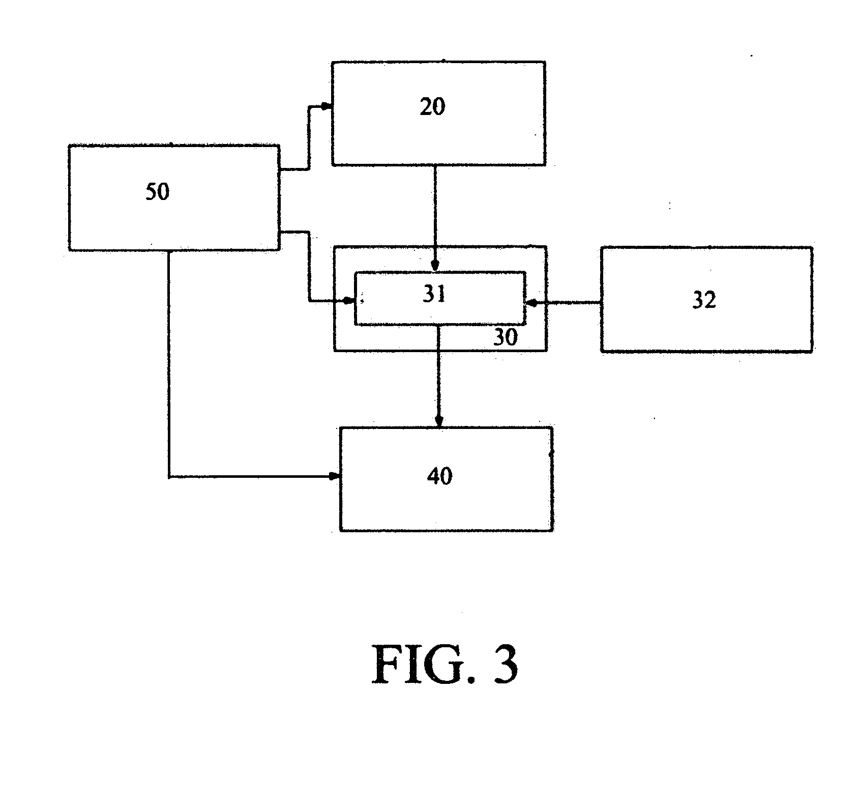
[0029]In the following descriptions and explanations, reference is made to the In order to understand better, please see following descriptions and explanations for a preferred embodiment with reference to FIGS. 1, 2, and 3. The invention of a wireless bike brake light comprises: a main body 10, an accelerometer 20, a control circuit 30, a lighting device 40, a power 50 and a fixing device 60; The main body 10, comprising a hollowed body base 11 and a transparent cover 12, is used to contain and protect the accelerometer 20, the control circuits unit 30, and the lighting device 40.

[0030]The accelerometer 20 is MEMS-structured and chip-shaped, which actually outputs a mixed signal of G-force and acceleration / deceleration conditions of bikes (Ex. if G-force exerted is −0.3 G and the bike accelerates at +0.5 G, then the accelerometer would output a signal magnitude equaling to +0.2 G) to the control circuits unit 30 for further analysis.

[0031]The control circuits unit 30 comprises a sw...


PUM


Abstract

This invention proposes a wireless bike brake light that can respond to braking when bikes are in motion. The invention employs a MEMS (micro electro mechanical system)-structured accelerometer chip as sensor to detect related signals. A control circuits unit processes the signals, and then sends appropriate brake light to following vehicles based. The features of the invention are that (1) It can provide extra security when serving as a brake light with independence of braking system, (2) It is easily to install and durable, (3) It can be also applied to such sports as skiing, skateboarding, etc. that are not equipped with apparent brake devices, and thus hard to incorporate brake lights.

Description

FIELD OF THE INVENTION[0001]This invention mainly employs a MEMS-structured accelerometer and controlling techniques to make possible a wireless bike brake light that can respond to not only “severe” braking, but also “light” braking.BACKGROUND OF THE INVENTION[0002]Prior Art 1: An old-fashioned wireless bike brake light, which emits radio to trigger brake light when a bike rider depresses the brake levels. The drawbacks include (1) a rider needs to install sensors on both brake levels of a bike, which actually causes a practical problem in installation because a different kind or brand of bike has the brake level of different shape or design. (2) For sports like skiing or snowboarding, such a product would not work because it does not have the apparent brake mechanisms that can serve as triggering devices.[0003]Prior Art 2: There were several severe brake light inventions that employ accelerometers, such as U.S. Pat. No. 6,249,219, a severe braking light system. It may work for res...

Claims


Application Information

Patent Timeline
Patent Type & Authority Applications(United States)
IPC IPC(8): B60Q1/50B62J6/00
CPCB60Q1/444B62J2006/008B62J6/04B60Q2900/30B62J6/165
Inventor LU, YEN-HO
Owner LU YEN HO
Why Eureka
Try Eureka