Multiple input multiple output communication apparatus

a communication apparatus and input-output technology, applied in the field of communication apparatus, can solve the problems of not being able to construct such an antenna, null direction of the antenna, and not always the most suitable antenna selection method

Inactive Publication Date: 2007-09-06
FUJITSU LTD
View PDF9 Cites 12 Cited by
  • Summary
  • Abstract
  • Description
  • Claims
  • Application Information

AI Technical Summary

Benefits of technology

[0016] The MIMO communication apparatus according to the present invention comprises a plurality of antennas for conducting wireless communications, a switch for switching the antennas, and a control device. The control device determines a combination of at least two antennas used for the MIMO communication from the antennas in accordance with a prescribed selection reference, and outputs a selection signal causing selection of the determined antennas to the switch.
[0017] In the first MIMO communi

Problems solved by technology

Accordingly, it is desired that human controllable G(θ, φ) is spatially uniform (nondirectional antenna) for improving a received power, however, it is not practicable to construct such an antenna.
As a result, a case occurs that a directivity of an antenna is null in the direction

Method used


Image

  • Multiple input multiple output communication apparatus
  • Multiple input multiple output communication apparatus
  • Multiple input multiple output communication apparatus

Examples


Embodiment Construction

[0025] Hereinbelow, the most preferred embodiment for implementing the present invention is explained in detail, by referring to the drawings.

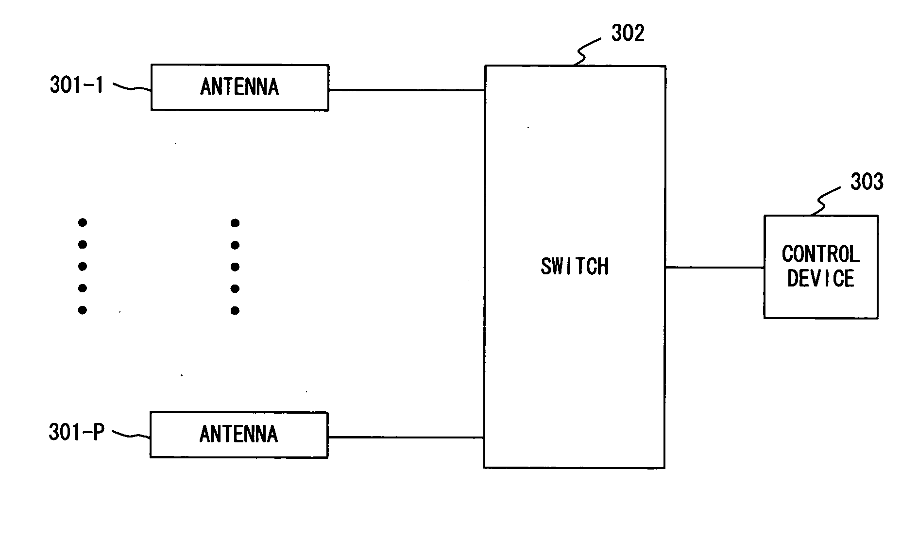
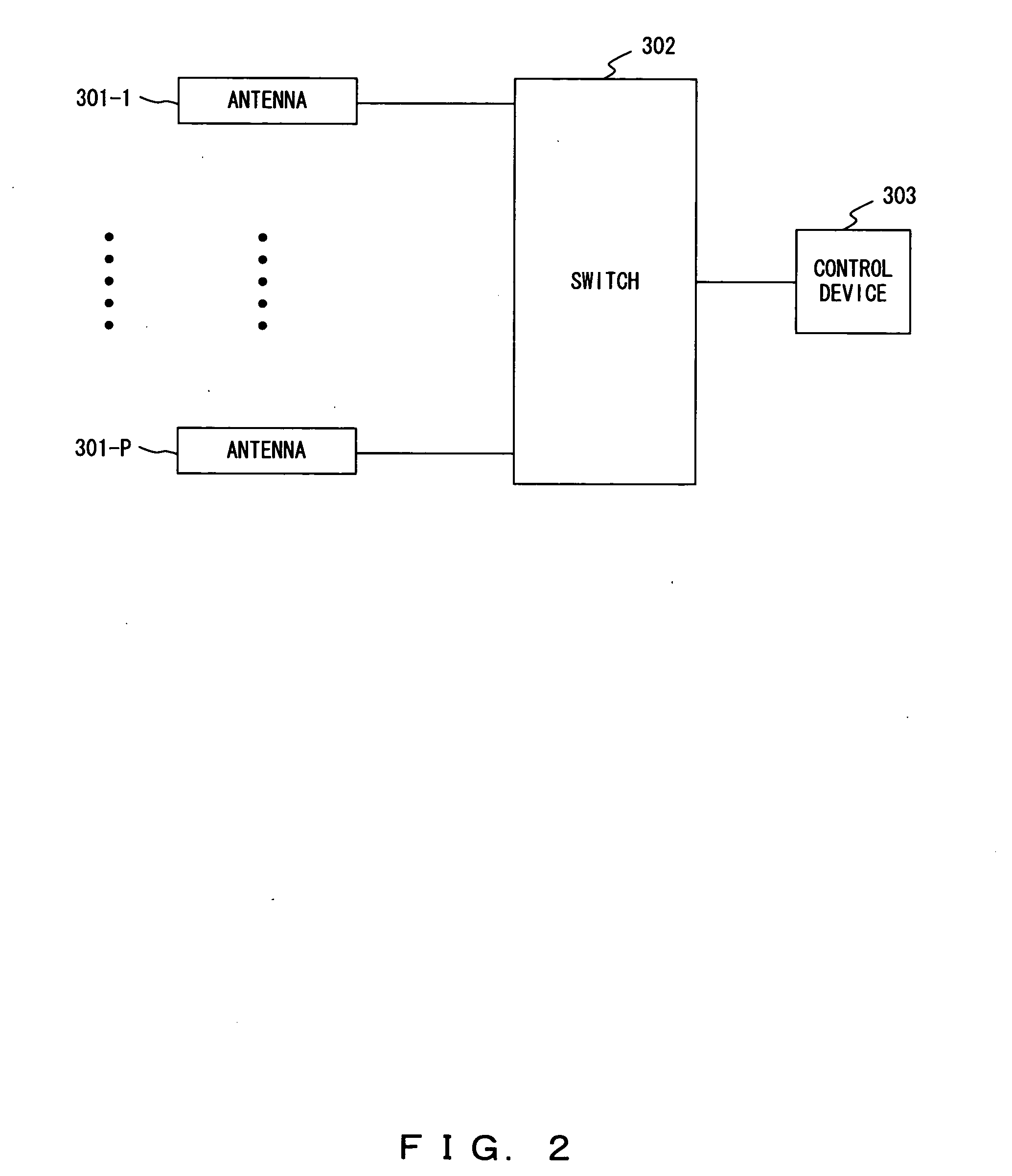
[0026]FIG. 2 shows a principle of a MIMO communication apparatus according to the present invention. The MIMO communication apparatus of FIG. 2 comprises P number of antennas 301-1 through 301-P for conducting wireless communications, a switch 302 for switching the antennas 301-1 through 301-P, and a control device 303.

[0027] The control device 303 determines a combination of at least two antennas used for the MIMO communication from the antennas 301-1 through 301-P in accordance with a prescribed selection reference, and outputs a selection signal causing the selection of the determined antennas to the switch 302.

[0028] In the first principle, the control device 303 uses signal to interference plus noise ratio (SINR) information and spatial fading correlation information as the prescribed selection reference.

[0029] In the second principle...


PUM


Abstract

Signal to interference plus noise ratio information, delay spread information, or condition number information of a channel matrix in a multiple input multiple output communication are taken into account in addition to spatial fading correlation information for selecting a combination of at least two antennas from a plurality of antennas, then, the multiple input multiple output communication is conducted by using the selected antennas.

Description

BACKGROUND OF THE INVENTION [0001] 1. Field of the Invention [0002] The present invention relates to a wireless communication system, and particularly to a communication apparatus in a MIMO (Multiple Input Multiple Output) system, which conducts wireless communications using a plurality of antennas for transmitting and receiving. [0003] 2. Description of the Related Art [0004] A received signal r in a wireless communication is given as a result of integrating the product of a directivity G(θ, φ) of an antenna and a characteristic H(θ, φ) of a propagation path, as shown in the equation below. r=∫0π⁢∫-ππ⁢G⁡(θ,ϕ)⁢H⁡(θ,ϕ)⁢ ⁢ⅆϕ⁢ ⁢ⅆθ(1)[0005] In the above equation, θ and φ respectively represent an azimuth angle and an elevation angle in the receiving side. Generally, because H(θ, φ) is a variable of natural phenomenon which a human can not control, and expresses an incoming wave distribution which is spatially polarized. Accordingly, it is desired that human controllable G(θ, φ) is spat...

Claims


Application Information

Patent Timeline
IPC IPC(8): H04M1/00H04J99/00
CPCH04B7/0874H04B7/0808
Inventor NAKAYA, YUUTA
Owner FUJITSU LTD
Why Eureka
Try Eureka