Radio communication method and radio base transmission station

a radio communication and radio base technology, applied in the field ofsignal transmission methods, can solve the problems of difficult to estimate the down link line information from the up link line information, especially in the fdd system, and achieve the effect of difficult adaptive array processing and difficult to estimate the down link line information

Inactive Publication Date: 2007-09-06
HITACHI LTD
View PDF5 Cites 38 Cited by
  • Summary
  • Abstract
  • Description
  • Claims
  • Application Information

AI Technical Summary

Benefits of technology

[0022]According to the present invention, a plurality of base transmission stations are combined to form an SDMA antenna pattern. Accordingly, for a user affected by a strong interference from an adjacent base transmission station, it is possible to perform signal transmission with a frequency or time which avoids the interference. By combination with a scheduler, a packet scheduling is enabled by avoiding a strong interference from an adjacent station.

Problems solved by technology

In a down link line for a signal transmission from a base transmission station to a terminal, when deciding the array weight, it is difficult to estimate the down link line information from the up link line information especially in the FDD system.
Accordingly, it is difficult to perform adaptive array processing for always assuring preferable C / I by adaptively changing the array weight.

Method used


Image

  • Radio communication method and radio base transmission station
  • Radio communication method and radio base transmission station
  • Radio communication method and radio base transmission station

Examples


first embodiment

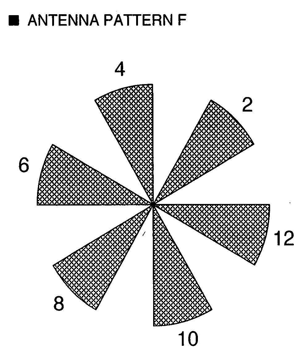
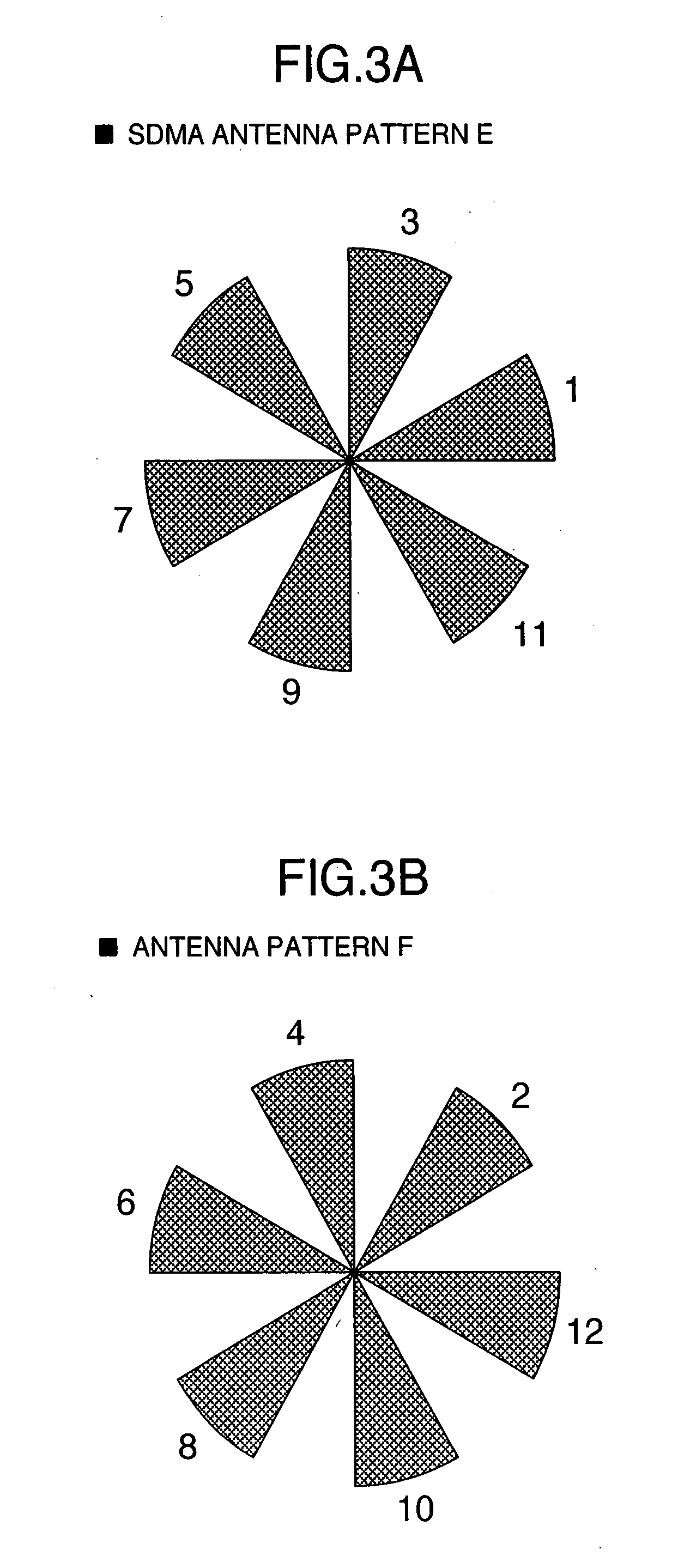
[0042]The first embodiment will be explained through an example of the system simultaneously transmitting six beams shown in FIG. 3A and FIG. 3B.

[0043]FIG. 3A shows an antenna pattern E (1, 3, 5, 7, 9, 11) simultaneously transmitting a signal to six users and FIG. 3 B shows an antenna pattern F (2, 4, 6, 8, 10, 12) also transmitting a signal simultaneously to six users. Antenna patterns between adjacent cells are arranged, for example, as shown in FIG. 8. FIG. 8 shows hexagonal cells representing service areas of the respective base transmission stations. A base transmission station is arranged at the center of each hexagonal area. There is shown a cell named “d” in the center of the figure. In the cell, “EEEEFFFF” is written. This indicates the correspondence between the frequency and the antenna pattern. The leftmost first E represents an antenna pattern E of the lowest frequency. The next frequency band is also E pattern. Four E patters appear continuously and then F pattern appe...

second embodiment

[0065]Referring to FIG. 9, explanation will be given on a This embodiment uses four antenna patterns as shown in FIG. 4A to FIG. 4D.

[0066]When the four antenna patterns of FIG. 4A to FIG. 4D are compared to one another, the antenna pattern A of FIG. 4A and the antenna pattern C of FIG. 4C have opposite beam directions, indicating a high orthogonality on the spatial axis. Moreover, the same holds true with the antenna pattern B of FIG. 4B and the antenna pattern D of FIG. 4D. Conversely, when the antenna pattern A is compared to the antenna pattern B, for example, beams 1 and 2 are in the adjacent directions and there is a possibility that the side lobes may overlap with the main lobes mutually and hence it can not necessarily be said that the orthogonality is high. This means that when the antenna pattern A and the antenna pattern B are in a pair, the both antenna patterns may give interfere to a certain terminal with a high possibility. In other words, when the antenna pattern A o...


PUM


Abstract

An antenna pattern assigning method capable of avoiding interference between a plurality of base transmission stations constituting a radio system in a cellular type broad band communication. In the radio system, when assigning a fixed beam pattern different for each frequency, each of the radio base transmission station devices transmits a radio wave having a directivity pattern having a peak in the same direction in two or more different frequencies, and between adjacent radio base transmission station devices, radio transmission is performed by using different directivity patterns in the two or more frequencies.

Description

INCORPORATION BY REFERENCE[0001]The present application claims priority from Japanese application JP2006-058853 filed on Mar. 6, 2006, the content of which is hereby incorporated by reference into this application.BACKGROUND OF THE INVENTION[0002]The present invention relates to a signal transmission method in a base transmission station device of cellular radio communication and in particular, to a beam forming method for transmitting a signal in a particular direction by using a plurality of antenna elements such as an array antenna.[0003]In the cellular radio communication, an array antenna is used to improve an antenna gain and reduce interference to other communication. The array antenna uses a signal processing technique called “beam forming”, i.e., a signal transmission or a signal reception is performed by applying an array weight made of a complex number to a plurality of antenna elements so as to give a directivity pattern for emphasizing the antenna gain in a particular d...

Claims


Application Information

Patent Timeline
Patent Type & Authority Applications(United States)
IPC IPC(8): H04M1/00
CPCH01Q25/00H01Q1/246
Inventor KUWAHARA, MIKIOFUJISHIMA, KENZABUROTAIRA, MASANORI
Owner HITACHI LTD
Why Eureka
Try Eureka