
In-vehicle apparatus

Inactive Publication Date: 2007-09-06
SONY CORP
View PDF7 Cites 8 Cited by
  • Summary
  • Abstract
  • Description
  • Claims
  • Application Information

AI Technical Summary

Benefits of technology

[0010] On the other hand, where the microphone is attached to the in-vehicle apparatus, the problems concerning the laying space for the wiring member and laying-around of the wiring member are dissolved. However, in order to pick up the sound (voice) with good tone quality, it would be necessary to provide the appearance surface (design surface) of the in-vehicle apparatus with a hole or opening for guiding the sound to the microphone, which is disadvantageous from the viewpoint of enhancing the appearance quality and enhancing the degree of freedom in design.
[0011] Thus, there is a need for an in-vehicle apparatus which unnecessitates a wiring member for disposing a microphone and which is advantageous in view of securing the degree of freedom in designing.
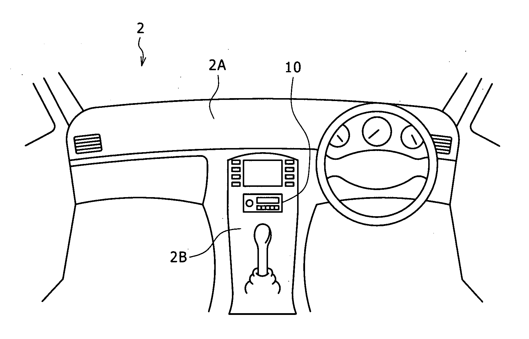
[0014] Therefore, unlike in the case where the microphone is attached to a location in the vehicle compartment remote from the in-vehicle apparatus, there is no need for a wiring member for connection between the microphone and the in-vehicle apparatus, so that the need for a laying space for a wiring member is eliminated, and the work of arranging the in-vehicle apparatus can be carried out easily. In addition, it is unnecessary for the outside surface of the lid where the in-vehicle apparatus fronts on the vehicle compartment to be provided with a hole or opening for guiding a sound to the microphone, which is advantageous in view of enhancing the appearance quality and enhancing the degree of freedom in design.

Problems solved by technology

However, since the microphone and the in-vehicle apparatus are connected to each other by a wiring member, there is need for the laying space for the wiring member.
Besides, there is a disadvantage that laying-around of the wiring member is intricate.
On the other hand, where the microphone is attached to the in-vehicle apparatus, the problems concerning the laying space for the wiring member and laying-around of the wiring member are dissolved.
However, in order to pick up the sound (voice) with good tone quality, it would be necessary to provide the appearance surface (design surface) of the in-vehicle apparatus with a hole or opening for guiding the sound to the microphone, which is disadvantageous from the viewpoint of enhancing the appearance quality and enhancing the degree of freedom in design.

Method used


Image

  • In-vehicle apparatus
  • In-vehicle apparatus
  • In-vehicle apparatus

Examples


first embodiment

[0111] Next, the case of conducting hands-free conversation by use of the hands-free system of the in-vehicle apparatus 10 will be described.

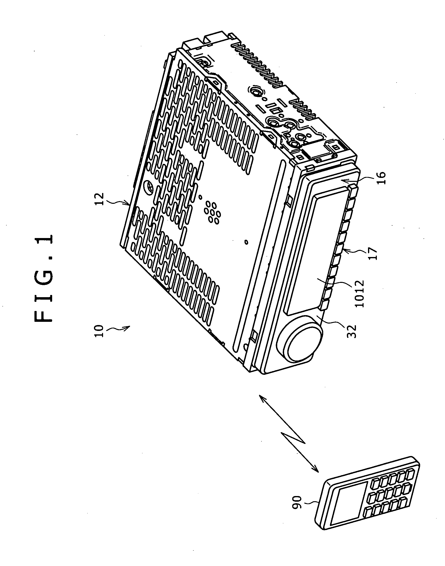
[0112] Incidentally, the description will be made on the assumption that the in-vehicle apparatus 10 is in a use condition with the front surface 14 of the apparatus body 12 closed with the lid 16.

[0113] As shown in FIG. 4, when the user's cellular phone 90 supplied with power source is brought into the vehicle compartment, a Bluetooth radio line is established between the radiocommunication unit 9002 of the cellular phone 90 and the radiocommunication unit 1020 of the in-vehicle apparatus 10.

[0114] When a telephone call is made from the telephone set 94 on the other end side of line to the user's cellular phone 90 in the condition where the radio line is established through the radiocommunication unit 9002 of the cellular phone 90 and the radiocommunication unit 1020, a call reception sound is issued from the cellular phone 90.

[0115] When ...

second embodiment

[0141] Now, a second embodiment of the present invention will be described below.

[0142] In the first embodiment above, the case where the cellular phone 90 and the in-vehicle apparatus 10 are connected to each other by a Bluetooth or other radio line at the time of performing hands-free conversation has been described. In the second embodiment, on the other hand, the cellular phone 90 and the in-vehicle apparatus 10 are connected to each other by wiring.

[0143]FIG. 27 is a block diagram showing the configuration of a control system in the in-vehicle apparatus 10 according to the second embodiment, in which the same or equivalent parts to those in the first embodiment above are denoted by the same symbols as used above.

[0144] As shown in FIG. 27, in the second embodiment, the hands-free conversation system includes a speaker 18, a microphone 20, an audio output unit 1006, an audio input unit 1008, an interface unit 1030, and a control unit 1014.

[0145] The interface unit 1030 is pr...


PUM


Abstract

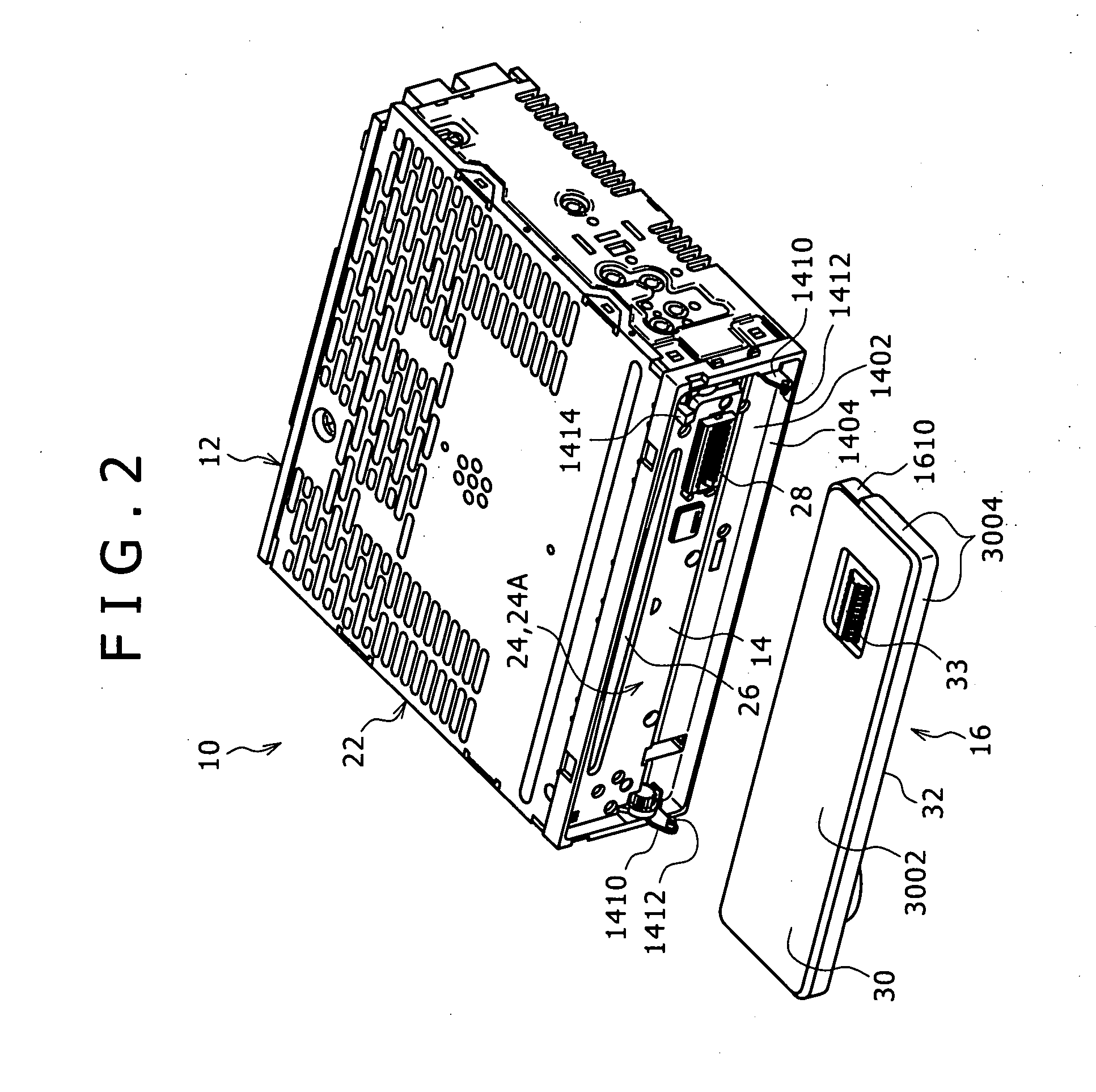
An in-vehicle apparatus including: an apparatus body; a front surface of the apparatus body; and a lid configured to open and close the front surface. A microphone directed to the front side of the front surface in the condition where the lid is opened is provided at the front surface of the apparatus body. A gap for communication between the location, where the microphone is provided, of the front surface and the outside is secured between the front surface and the lid in the condition where the front surface of the apparatus body is closed with the lid.

Description

CROSS REFERENCES TO RELATED APPLICATIONS [0001] The present invention contains subject matter related to Japanese Patent Application JP 2006-040495 filed with the Japanese Patent Office on Feb. 17, 2006, the entire contents of which being incorporated herein by reference. BACKGROUND OF THE INVENTION [0002] 1. Field of the Invention [0003] The present invention relates to an in-vehicle apparatus. [0004] 2. Description of the Related Art [0005] There has been provided a hands-free conversation system which is disposed in a compartment of an automobile and through which talking can be performed without holding a cellular phone by hand (refer to Japanese Patent Laid-open No. 2001-103547). [0006] The hands-free conversation system has a microphone for picking up a sound (voice) and a speaker for generating a sound (voice), which are connected to a cellular phone through a wired circuit or a wireless circuit so as to enable communication. The user can perform hands-free conversation in th...

Claims


Application Information

Patent Timeline
IPC IPC(8): H04M1/00B60R11/02H04R1/02
CPCB60R11/02B60R11/0247B60R11/0264H04M1/6091B60R2011/0294G11B31/00G11B33/027B60R2011/008
Inventor KURAUCHI, SEIJIKOBAYASHI, TOSHIAKINISHIOKA, YUICHIROARAI, HIROYUKITANAKA, HISAHIRO
Owner SONY CORP
Learn More