Spacer for a medical instrument

Active Publication Date: 2007-09-13
KARL STORZ GMBH & CO KG
View PDF10 Cites 61 Cited by
  • Summary
  • Abstract
  • Description
  • Claims
  • Application Information

AI Technical Summary

Benefits of technology

[0015] The provision of a spacer now makes it possible in principle to vary the depth of insertion, in particular to limit this depth of insertion. By providing a distal abutment which can come to bear on the body, the depth of insertion of the shaft is limited by the spacer and no longer by other structural parts of the instrument. The spacer comprises a spacer element which extends along a length portion of the shaft and which either itself limits the extent by which the depth of insertion is limited or at least determines this extent via the distal abutment. By providing a device for releasably mounting the spacer on the instrument, the spacer can be fitted on the medical instrument when the need arises. Moreover, the fact that it is releasable means that the spacer can be set to respectively desired spacer positions

Problems solved by technology

It is not possible to rule out the possibility of the distally protruding trocar mandrel causing injuries inside the body as the trocar sleeve is being driven in.
If a trocar mandrel is used which is considerably longer than the trocar

Method used


Image

  • Spacer for a medical instrument
  • Spacer for a medical instrument
  • Spacer for a medical instrument

Examples


Embodiment Construction

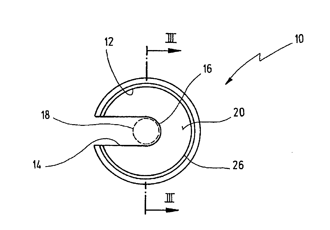
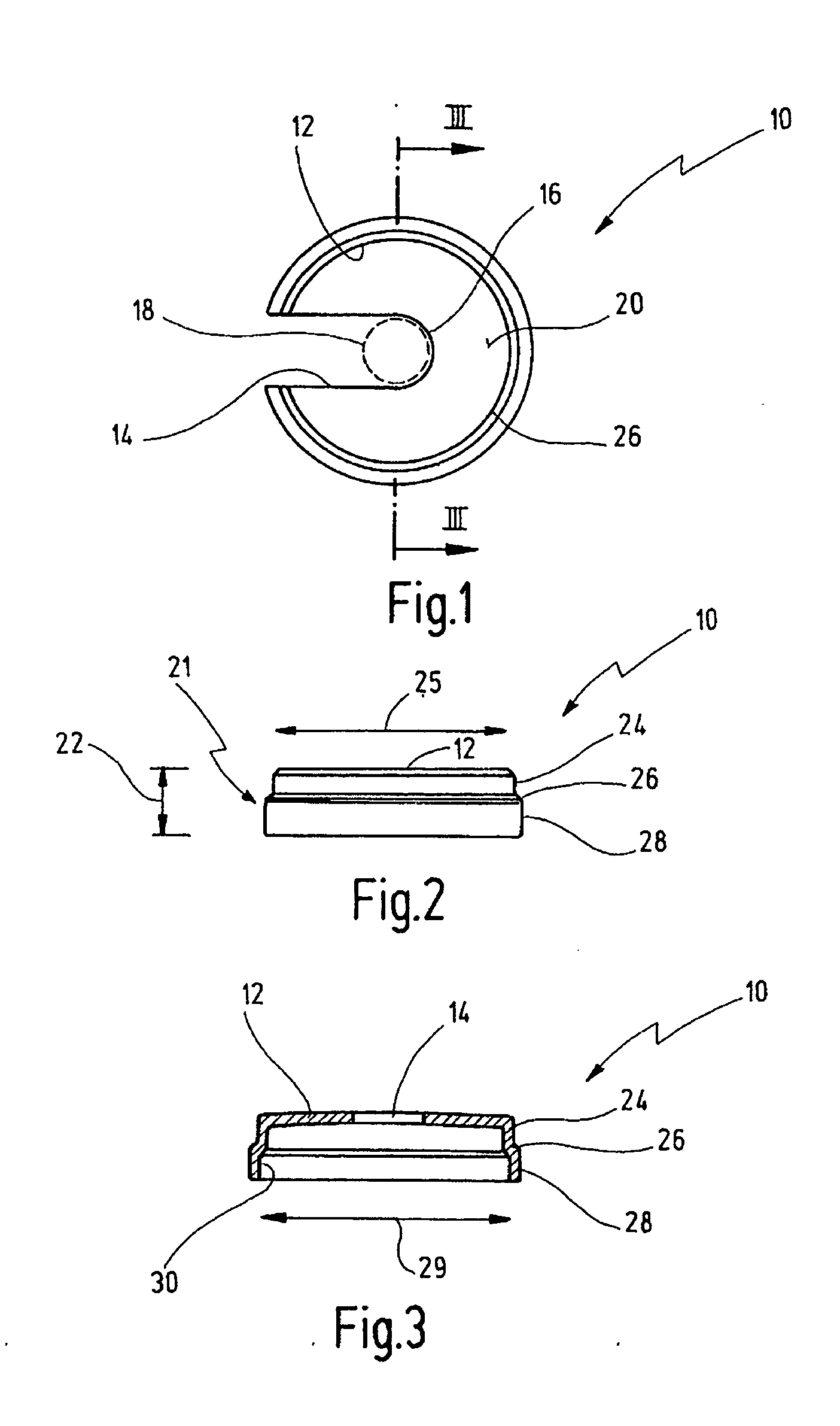
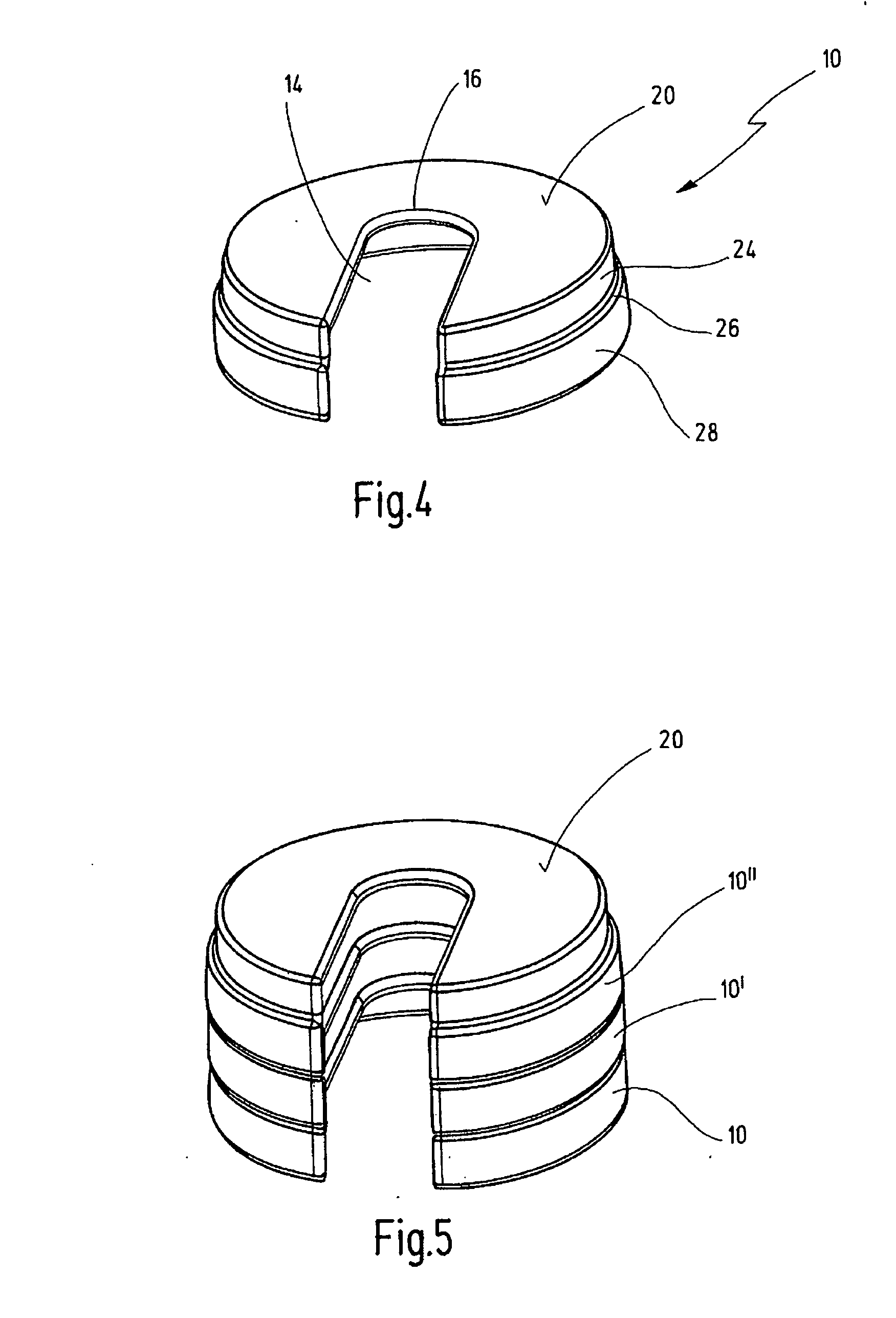
[0050] An illustrative embodiment of a spacer shown in FIGS. 1 to 4 is designated in its entirety by reference number 10.

[0051] The spacer 10, at the distal end, is roughly in the form of a disk 12 in which a laterally opening slit aperture 14 Is formed. The slit aperture 14 has a circular base 16 whose diameter and position are such that the spacer 10 can be pushed from the side onto a shaft 18 of an instrument that will be described below, specifically in such a way that the shaft 18 then comes to lie approximately in the center of the slit disk 12, as is indicated by the dashed line in FIG. 1.

[0052] It will be seen from the side view in FIG. 2 that a first annular flange 24 extends from the disk 12 and merges via a shoulder 26 into a second annular flange 28 of somewhat greater diameter. These form a spacer element 21 that extends along a length portion 22.

[0053] It will be seen from the views in FIGS. 2 and 3 that the external diameter 25 of the first annular flange 24 corres...


PUM


Abstract

The spacer serves for limiting the depth of insertion of a shaft of a medical instrument into a body of a patient. The spacer has a distal abutment for bearing on a body of a patient. The spacer has a spacer element extending along a length section of the shaft of the medical instrument. A device for releasably mounting the spacer on the shaft has an aperture via which the spacer can be mounted laterally to the shaft. For it the aperture is designed as a lateral slit aperture.

Description

BACKGROUND OF THE INVENTION [0001] The invention relates to a spacer for limiting the depth of insertion of a shaft of a medical instrument into a body. [0002] In minimally invasive surgery, medical instruments have become established that can be introduced into the body through a small incision, for the purpose of carrying out an intervention in the interior of the body. [0003] The medical instruments have a shaft which is guided through the incision and into the body, for example through the abdominal wall and into the abdominal cavity. Natural orifices such as the vagina or anus can also be used for introducing Instruments of this kind. The shaft itself can be of a solid design, for example in the case of a liver retractor, a trocar mandrel or other maneuvering instruments, or it can be designed as a hollow shaft. [0004] Different types of instruments for surgeries can be guided through the hollow shaft. [0005] At the proximal end, the shaft in most cases terminates in a structur...

Claims


Application Information

Patent Timeline
IPC IPC(8): A47F7/00
CPCA61B17/29A61B17/320016A61B17/3417A61B2019/462A61B2019/304A61B2019/306A61B2017/3492A61B2090/034A61B2090/036A61B2090/062
Inventor WALLWIENER, DIETHELMBRUCKER, SARA
Owner KARL STORZ GMBH & CO KG
Why Eureka
Try Eureka