Electric Field Light Emitting Element

a technology of light emitting element and electric field, which is applied in the direction of discharge tube/lamp details, discharge tube luminescnet screen, discharge tube/lamp details, etc., can solve the problems of uneven luminance throughout the element, affecting the light intensity of the element, and extremely limited materials for forming the organic el elemen

Inactive Publication Date: 2007-09-13
TOYOTA IND CORP
View PDF6 Cites 24 Cited by
  • Summary
  • Abstract
  • Description
  • Claims
  • Application Information

AI Technical Summary

Benefits of technology

[0024] Accordingly, it is an objective of the present invention to provide an electroluminescence element having a novel configuration for bringing a luminance distribution of an element into a desired state. “Desired states” include a state in which the luminance is substantially uniform throughout the element, a state in which the luminance of the central part is higher than that of the opposite sides or the periphery, and a state in which the luminance of any display area in an image or the like is high.

Problems solved by technology

However, mere employment of the above structure does not lead to completion of the organic EL element, and for example, at least one electrode should be capable of injecting electric charges (holes or electrons) into the organic layer and have transparency to light emitted at the organic light emitting region for extracting light to outside the element.
Therefore, materials for forming the organic EL element are extremely limited, and in most cases, there is no other choice but to use a material having a high volume resistivity for the transparent electrode and the organic layer.
Thus, there arises a problem that the current density at the organic layer varies depending on the position.
Since there are locations where a large amount of current passes and where only a small amount of current passes, luminance unevenness occurs throughout the element.
The luminance of the organic electroluminescence element becomes high as the amount of passing current increases (see, for example, Non-Patent Document 1), and therefore if there are locations where a large amount of current passes and where a small amount of current passes, a difference in luminance occurs between the locations, resulting in luminance unevenness.
However, the size of an apparatus such as a portable terminal in which the organic EL element is incorporated is limited, and therefore the size of the organic EL element is also limited.
Thus, provision of a large number of unloading portions as in the prior art is effective for solving the problem described above, but is extremely difficult to employ from a practical viewpoint.
In addition, provision of a plurality of terminal portions leads to a problem that the proportion of the wirings for connecting the terminal portions to external drive circuit in the apparatus increases.
This prior art is appropriately employed, but cannot completely solve the problem described above.
These prior arts can be appropriately employed, but it is extremely difficult from a practical viewpoint to change the thickness of each layer on a position-by-position basis in production of the organic EL element.
In addition, in an inorganic electroluminescence element (hereinafter referred to as inorganic EL element as appropriate), which is an electroluminescence element, similar problems have arisen.

Method used


Image

  • Electric Field Light Emitting Element
  • Electric Field Light Emitting Element
  • Electric Field Light Emitting Element

Examples


Embodiment Construction

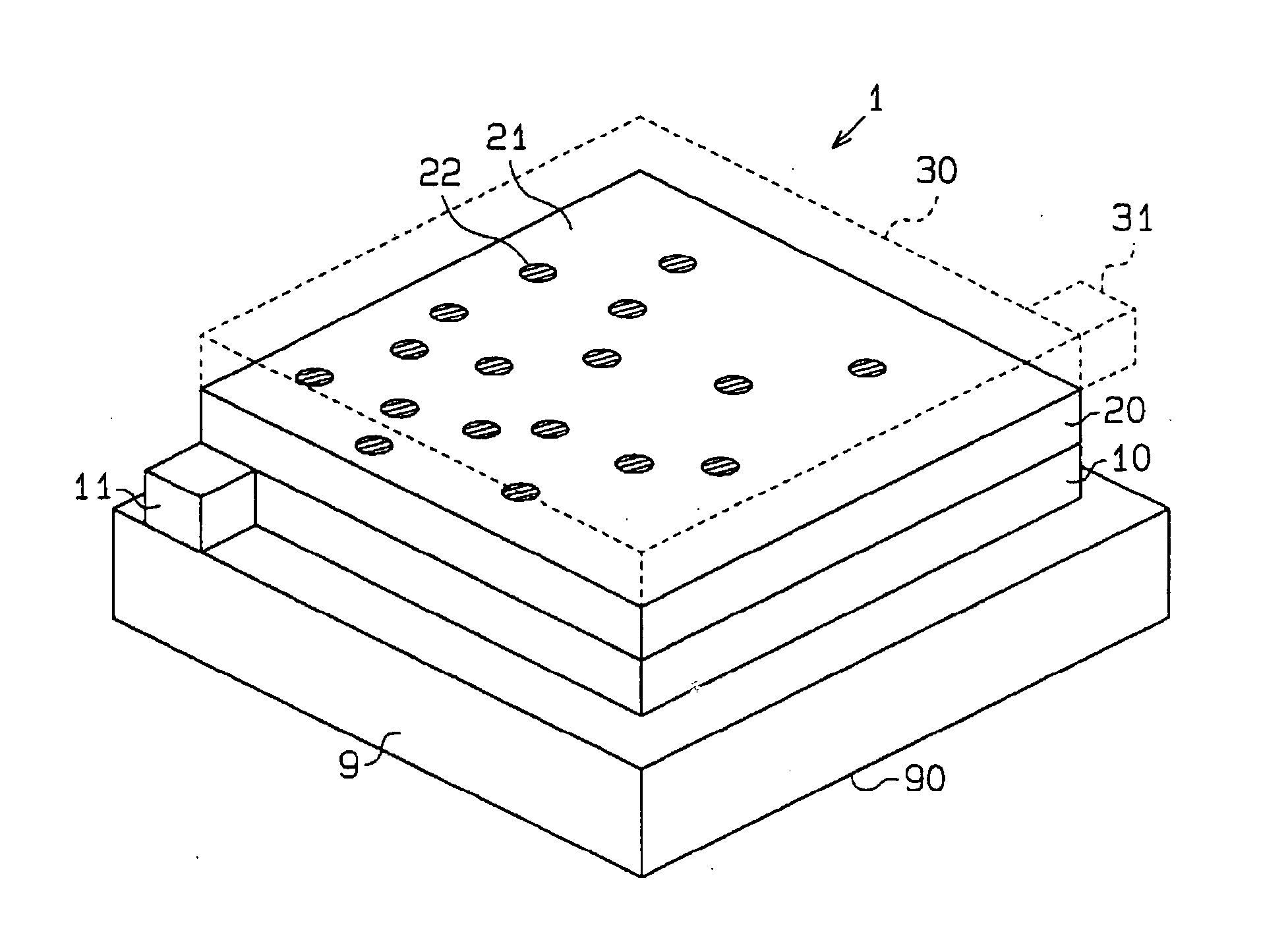
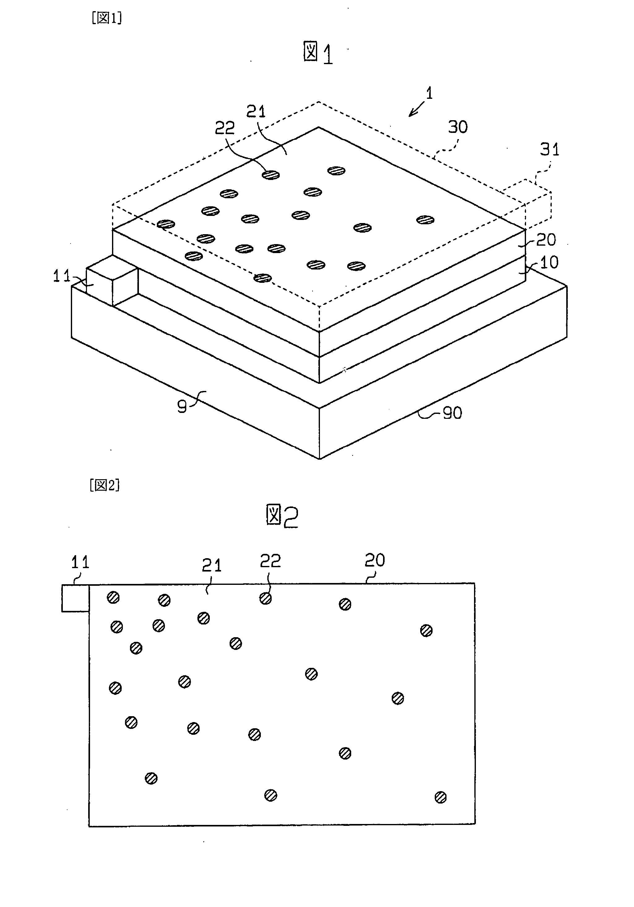
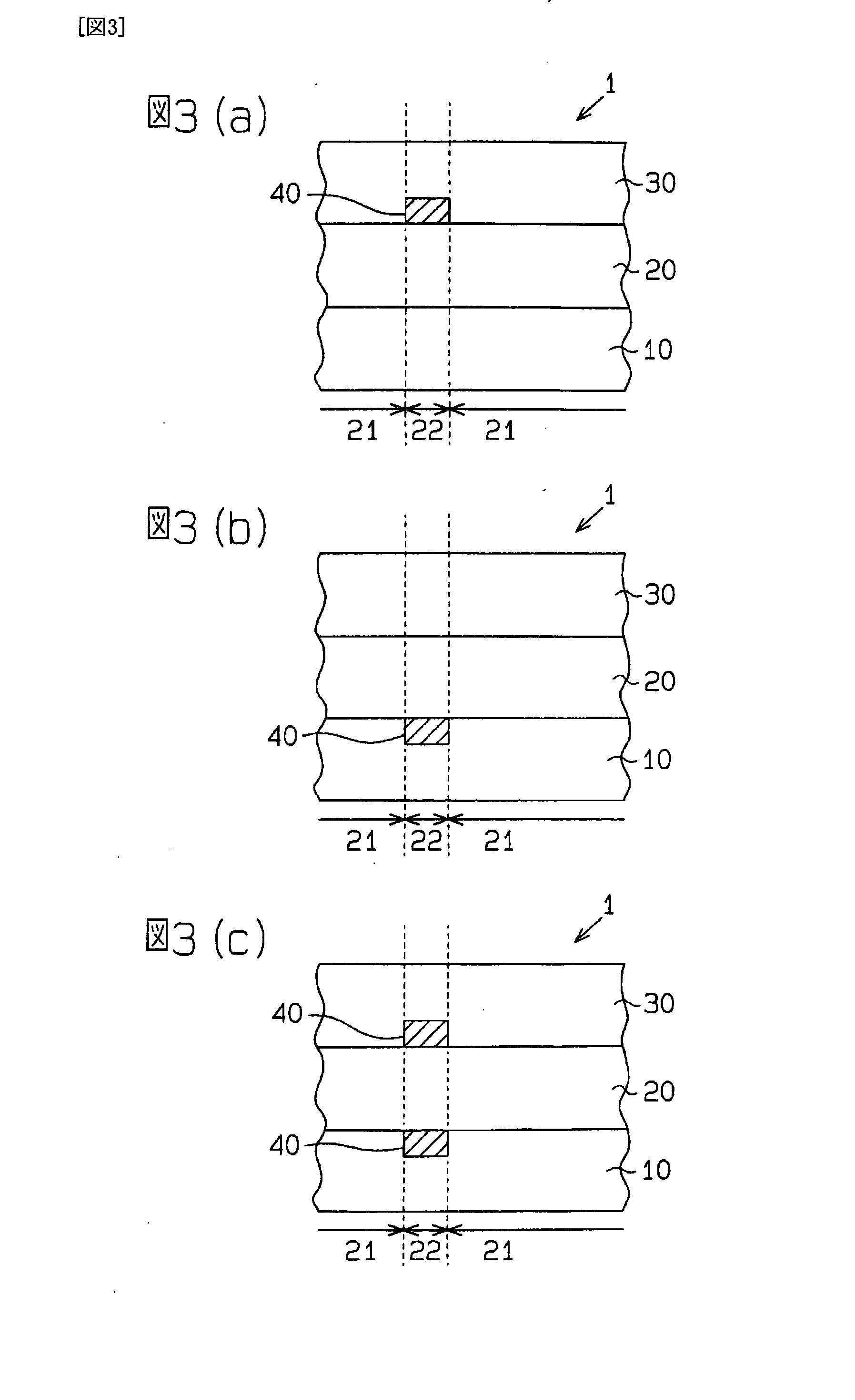
[0054] An electroluminescence element according to one embodiment will be described below with reference to FIGS. 1 to 4. In this embodiment, the electroluminescence element is an organic EL element having a substantially uniform luminance throughout the element as a desired state of the luminance distribution of the element. In FIGS. 1 to 4, same, equivalent or like members are given same numbers. In addition, FIGS. 1 to 4 do not represent the actual organic EL element, but schematically show its configuration for explaining its configuration and the like, and the dimension of one or several parts is extremely exaggerated. In addition, the hatching in the cross-sectional view is omitted in some cases.

[0055]FIG. 1 shows a schematic perspective view of a bottom emission type organic EL apparatus in which an organic EL element 1 according to the present invention is deposited on a transparent substrate 9, and light is extracted to outside from the side of the transparent substrate 9....


PUM


Abstract

An organic EL element that is an electroluminescence element has at least an organic layer held between a pair of electrodes. At least an electrode made of material having a higher volume resistivity, of the pair of electrodes, is formed in a flat form. The organic layer is provided with a plurality of non-light emitting portions. The non-light emitting portions are provided so that a larger number of non-light emitting portions exist per unit area at a position physically closer to the position of a terminal portion at which the electrode made of material having the higher volume resistivity is connected to an external connection terminal. As a result, the level of current passing per unit area is substantially uniform at each position on the element.

Description

TECHNICAL FIELD [0001] The present invention relates to an electroluminescence element having at least a light emitting layer held between a pair of electrodes. BACKGROUND ART [0002] Previously, displays, lighting systems and the like using an organic electroluminescence element (hereinafter referred to as an organic EL element as appropriate), which is an electroluminescence element, have been proposed. The organic EL element has a structure in which an organic layer having an organic light emitting region containing an organic light emitting material is held between a pair of electrodes. [0003] However, mere employment of the above structure does not lead to completion of the organic EL element, and for example, at least one electrode should be capable of injecting electric charges (holes or electrons) into the organic layer and have transparency to light emitted at the organic light emitting region for extracting light to outside the element. In addition, for the organic layer, a...

Claims


Application Information

Patent Timeline
Patent Type & Authority Applications(United States)
IPC IPC(8): H01J1/62H01L51/52H05B33/14H05B33/22H05B33/26
CPCH01L51/5203H01L2251/5361H01L51/5262H10K50/805H10K50/85H05B33/14H05B33/22H05B33/26
Inventor KATO, YOSHIFUMITAKEUCHI, NORIHITOKAWAUCHI, HIROYASUISHIKAWA, HARUYUKIMIURA, HIROYUKI
Owner TOYOTA IND CORP
Why Eureka
Try Eureka