Display device

a technology of a display device and a light guide plate, which is applied in the direction of lighting and heating apparatus, planar/plate-like light guides, instruments, etc., can solve the problems of degrading display quality, adding to manufacturing costs, and dislocating the optical sheet and the light guide plate, so as to reduce manufacturing costs, reduce manufacturing costs, and reliably regulate the displacement of optical sheets

Inactive Publication Date: 2007-09-13
MITSUBISHI ELECTRIC CORP
View PDF4 Cites 8 Cited by
  • Summary
  • Abstract
  • Description
  • Claims
  • Application Information

AI Technical Summary

Benefits of technology

[0010] The invention has been accomplished in view of the above problems. An object of the invention is to provide a display device using a light source capable of reliably regulating the displacement of an optical sheet and a light guide plate without degrading the display quality as well as capable of decreasing the manufacturing costs and reducing the frame size.

Problems solved by technology

However, if smaller protruding portions for position regulation are provided on the optical sheet and the light guide plate include so as not to influence the frame area of the display device, this results dislocation of the optical sheet and the light guide plate due to impact.
This involves reduced number of light source boards segmented thus adding to the manufacturing costs.
Further, the optical sheet is deformed by the light source board, which degrades the display quality.

Method used


Image

  • Display device
  • Display device
  • Display device

Examples


embodiment 1

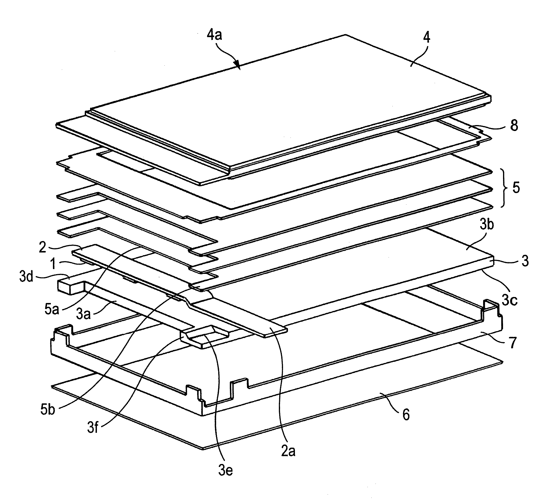
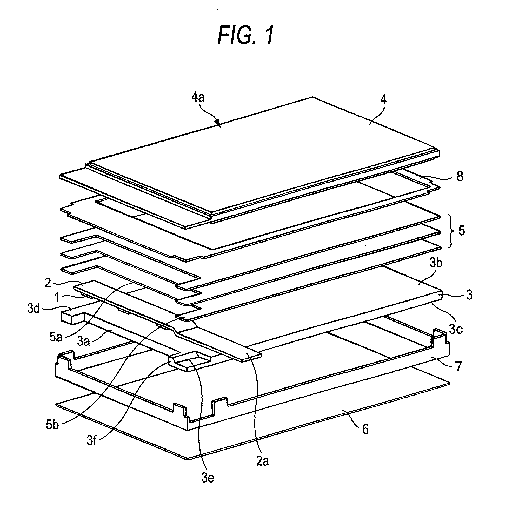
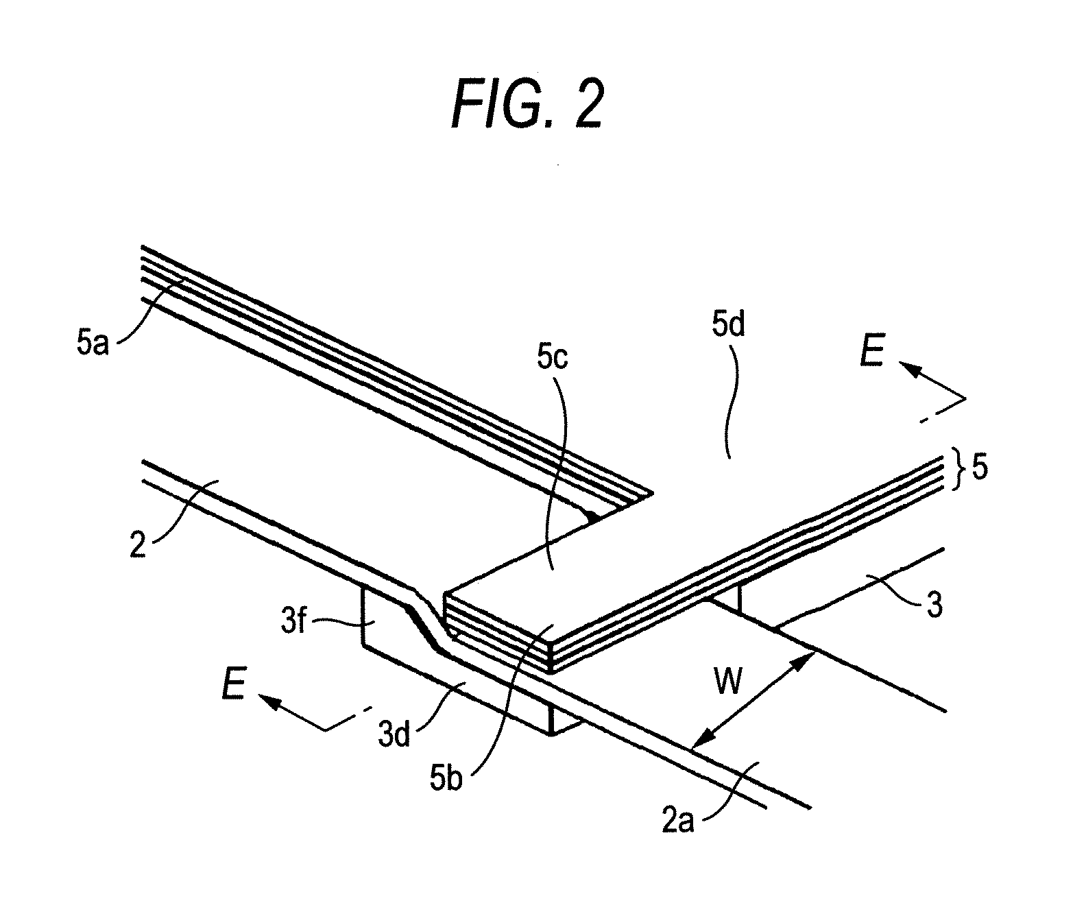
[0022]FIG. 1 is an exploded perspective view of a display device in Embodiment 1 of the invention. FIG. 2 is an enlarged view of a power feeding portion and its neighborhood of the light source board in Embodiment 1 of the invention. FIG. 3 is a cross-sectional view in the E-E direction of FIG. 2. FIG. 4 illustrates the shape of a protruding portion of the light guide plate in Embodiment 1 of the invention.

[0023] Referring to FIGS. 1 through 4, a plurality of light sources 1 using point light sources such as LEDs are arranged at a predetermined spacing and connected to a light source board 2. The light source board 2 includes a power feeding portion 2a and is arranged in close proximity to the side surface 3a of the light guide plate 3. Light from the light sources 1 is incident from the side surface 3a of the light guide plate 3 and emitted from the light emitting surface 3b of the light guide plate 3 (the light emitting surface refers to the top surface of the light guide plate 3...

embodiment 2

[0039] Embodiment 2 of the invention will be described referring to FIGS. 5 through 8. FIG. 5 is an exploded perspective view of a display device in Embodiment 2 of the invention. FIG. 6 is an enlarged view of a power feeding portion and its neighborhood of the light source board in Embodiment 2 of the invention. FIG. 7 is a cross-sectional view in the F-F direction of the display device in FIG. 6 with an optical sheet stacked thereon. FIG. 8 illustrates the shape of a protruding portion of the middle frame in Embodiment 2 of the invention. In FIGS. 5 through 8, a same component as that in FIGS. 1 through 4 is given the same sign.

[0040] As shown in FIGS. 5 through 8, in Embodiment 2, the plurality of optical sheets 5 have at least two protruding portion s 5b for position regulation formed on the side surface 5a facing the light source board 2 and are arranged facing the light emitting surface 3b of the light guide plate 3. On the light guide plate 3, there are no protruding portion...


PUM


Abstract

A display device includes: a light source; a light guide plate including a first plate surface that emits light incident from the light source, a second plate surface other than the first plate surface, and at least two protruding portions formed on the second plate surface; a light source board including the light source arranged thereon, the light source board arranged on the second plate surface; and an optical sheet including a first sheet surface arranged to face the first plate surface, a second sheet surface arranged to face the light source board, and at least two protruding portions formed on the second sheet surface.

Description

CROSS-REFERENCE TO RELATED APPLICATIONS [0001] This application is based upon and claims the benefit of priority from Japanese Patent Application No. 2006-056821, filed on Mar. 2, 2006, the entire contents of which are incorporated herein by reference. BACKGROUND OF THE INVENTION [0002] 1. Field [0003] The present invention relates to a display device using a light source board. [0004] 2. Description of the Related Art [0005] A display device, a display device using liquid crystal for example, is disclosed in FIG. 13 of JP-A-2004-349020. The display device includes: a liquid crystal panel that has a display surface; a light guide plate arranged on a surface opposite to the display surface of the liquid crystal panel to guide light to the liquid crystal panel; and a light source such as a light emitting diode (LED) arranged on a side surface of the light guide plate. By propagating light from a light source in a light guide plate and diffusing the light in a diffusion pattern provide...

Claims


Application Information

Patent Timeline
Patent Type & Authority Applications(United States)
IPC IPC(8): F21V7/04
CPCG02B6/0051G02B6/0091G02B6/0053G02B6/00G02B6/0001
Inventor ITO, ATSUSHIKAWANO, MASAYUKI
Owner MITSUBISHI ELECTRIC CORP
Why Eureka
Try Eureka