
Power line communications module and method

Inactive Publication Date: 2007-09-13
CURRENT TECH
View PDF99 Cites 118 Cited by
  • Summary
  • Abstract
  • Description
  • Claims
  • Application Information

AI Technical Summary

Benefits of technology

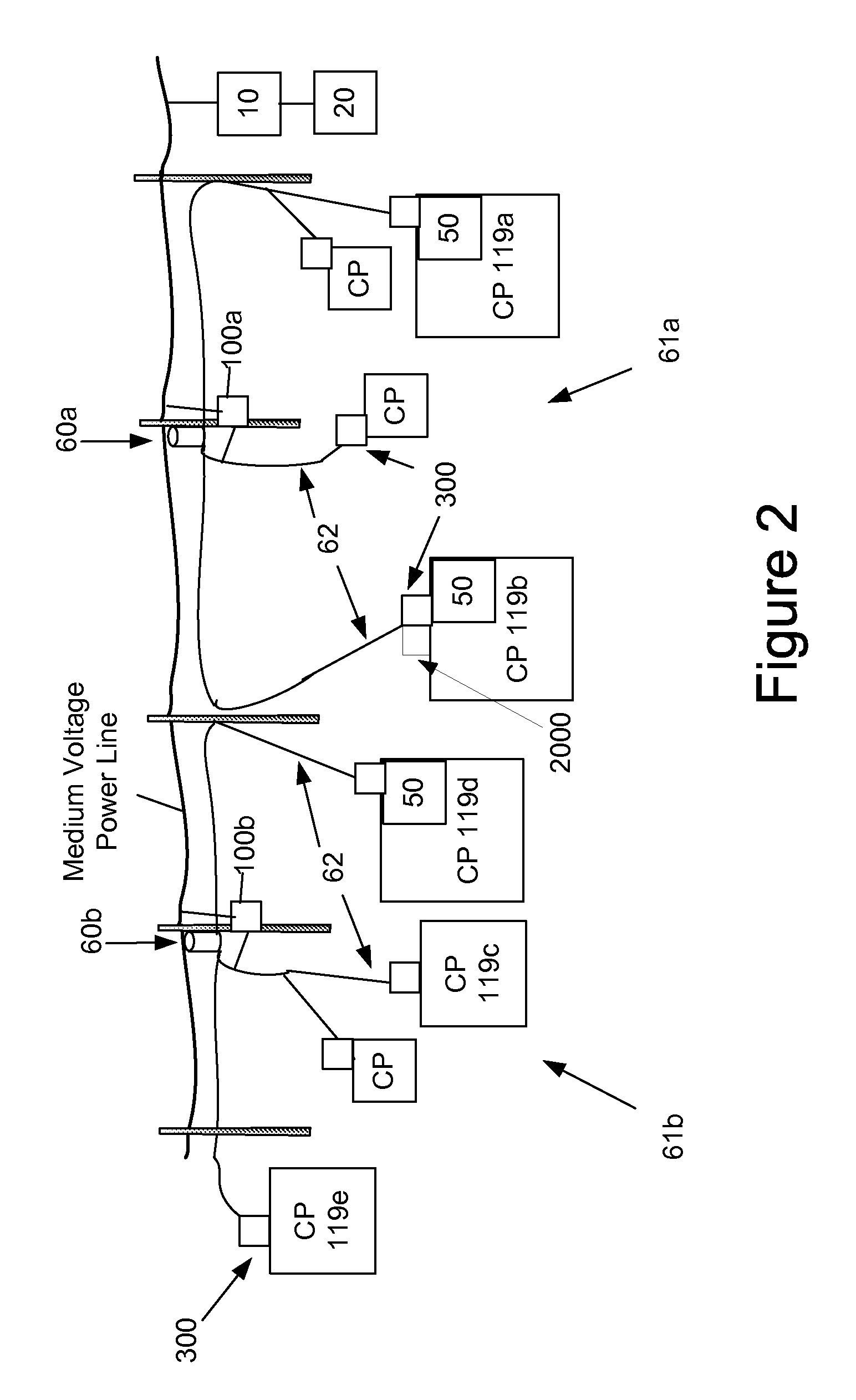
[0008] The present invention provides a system, device and method for providing communications to a plurality of customer premises via one or more external low voltage power lines. One embodiment of the system includes a power line communication device comprising a first modem configured to communicate over the one or more external low voltage power lines. The system further includes a plurality of wireless interface devices, each located at, and ext

Problems solved by technology

Power lines are not designed to provide high speed data communications and can be very susceptible to interference.
Additionally, federal regulations limit the amount of radiated energy of a power line communication system, which therefore limits the strength of the data signal that can be injected onto power lines (especially overhead power lines).
Consequently, due to the attenuation of power lines, communications signals typically will travel only a relatively short distance on power lines.
Additionally, in some instances the length of the LV power lines and associated attenuation can hamper or prevent reliable communications.
Additionally, ingress noise and noise from home appliances can degrade communications performance.
The high capital cost of replacing meters and building an AMR system in a large geographical area has hindered wide scale adoption of automated meter reading.

Method used


Image

  • Power line communications module and method
  • Power line communications module and method
  • Power line communications module and method

Examples


first embodiment

[0039] In the first embodiment, if repeating is enabled, and the data packet is successfully decrypted, the demodulated data packet is supplied to the processor 2040. Processor 2040 may process the data packet(s) and if the packet contains a command may perform one or more activities. Such commands and associated activities may include transmit utility data, update schedule of transmissions of utility data, disable repeating, enable repeating, receive and store new program code, store new IP address, and others. Processor 2040 may determine a data packet includes a command by any suitable method such as identify packets having a destination IP address corresponding to that of module 2000, which is stored in memory 2045. If the packet is not a command, the processor 2040 may supply the same received data packet back to the modem for transmission onto the LV conductors. In addition to supplying the data packet to the modem 2022, the processor 2040 also may supply information of the en...

second embodiment

[0042] In a second embodiment, instead of using different encryption keys the two power line interface circuits 2010 and 2020 may be configured to receive and transmit in different frequency bands to perform the logical isolation of networks described above. In this embodiment, the power line interface 2020 may not include frequency translation and be configured to receive and transmit in the 4-21 MHz band. Power line interface 2010 may include two frequency translation circuits—one for upbanding the output of the modem to the higher frequency band (e.g., 30-50 MHz) and one for downbanding the input of the higher frequency to 4-21 MHz used by the modem. Alternatively, the modem itself may communicate on 4-21 or 30-50 as selected by Processor 2040. In still another embodiment, a natively upbanded modem chip may be used. Thus, one frequency may be used to communicate with user devices and the other for communicating with the bypass device.

[0043] In operation, the module 2000 works sub...


PUM


Abstract

A system, device and method for providing communications to a plurality of customer premises via one or more external low voltage power lines is provided. One embodiment of the system includes a power line communication device comprising a first modem configured to communicate over the one or more external low voltage power lines. The system further includes a plurality of wireless interface devices, each located at, and external to, a respective one of the plurality of customer premises. Each wireless interface device may includes a first communication module configured to communicate with the power line communication device via the external low voltage power line; and a second communication module in communication with the first communication module and configured to provide wireless communications for one or more remote devices within the respective customer premises.

Description

CROSS REFERENCE TO RELATED APPLICATIONS [0001] This application is a continuation of, and claims priority to, U.S. patent application Ser. No. 11 / 341,646 filed Jan. 30, 2006, which is incorporated herein by reference in its entirety.FIELD OF THE INVENTION [0002] The present invention generally relates to data communications over a power distribution system and more particularly, to a communications module for communicating utility meter data and power line communications data. BACKGROUND OF THE INVENTION [0003] Well-established power distribution systems exist throughout most of the United States, and other countries, which provide power to customers via power lines. With some modification, the infrastructure of the existing power distribution systems can be used to provide data communication in addition to power delivery, thereby forming a power line communication system (PLCS). In other words, existing power lines that already have been run to many homes and offices, can be used t...

Claims


Application Information

Patent Timeline
IPC IPC(8): H04M1/00H04M9/00
CPCG01D4/004Y04S20/322Y02B90/242Y02B90/20Y04S20/30
Inventor CORCORAN, KEVIN F.MOLLENKOPF, JAMES D.BERNSTEIN, TERRY L.
Owner CURRENT TECH
Features
  • Generate Ideas
  • Intellectual Property
  • Life Sciences
  • Materials
  • Tech Scout
  • Unparalleled Data Quality
  • Higher Quality Content
  • 60% Fewer Hallucinations
Learn More