Ink ribbon cartridge and printer device

a printer device and ink ribbon technology, applied in printing devices, inking apparatus, printing, etc., can solve the problems of inconvenient use, inability to reduce the size of the device body, inhibit the provision of transfer mechanisms, etc., to achieve the effect of reducing size, smooth inserting, and increasing design flexibility

Inactive Publication Date: 2007-09-13
SONY CORP
View PDF0 Cites 84 Cited by
  • Summary
  • Abstract
  • Description
  • Claims
  • Application Information

AI Technical Summary

Benefits of technology

[0010] It is thus desirable to provide an ink ribbon cartridge offering ease of insertion to and removal from an ink ribbon cartridge holder, and a printer device to be attached with the ink ribbon cartridge.
[0013] According to the ink ribbon cartridge and the printer device to be attached with the ink ribbon cartridge in the embodiment of the invention, the ink ribbon cartridge can be smoothly inserted to and removed from the ink ribbon cartridge holder. This is because the guide section of the ink ribbon cartridge is guided by the guide support section formed to the ink ribbon cartridge holder with the cross section looking like a substantially square bracket shape while being supported thereby at surfaces, i.e., lower surface, side surfaces, and upper surface.
[0014] Moreover, the guide sections are formed to bulge at positions higher than the lower surfaces of a pair of housing sections formed to the ink ribbon cartridge. The lower surfaces of the guide sections are thus supported by the ink ribbon cartridge holder whose cross section looks like a substantially square bracket shape so that a space can be saved below the guide sections for disposition of the components on the side of the printer device. By disposing the components of the printer device in this space, this favorably contributes to the increase of design flexibility, the reduction of size, and the saving of space of the printer device.

Problems solved by technology

Such a space adds constraints for users where to place the printer device, and thus the users find it not convenient.
Moreover, because the ink ribbon cartridge is inserted to and removed from the side surface of the device body, such cartridge insertion and removal inhibits the provision of transfer mechanisms, e.g., printing medium and ink ribbon, on the side surface of the device body where an area is provided for allowing the ink ribbon cartridge to move or a hole is provided for cartridge insertion and removal.
This causes many restrictions, i.e., the device body cannot be reduced in size, and the design flexibility is reduced in terms of space saving.
Moreover, because the ink ribbon is inserted to and removed from the side surface of the device body, users have to face the front of the device body to insert the ink ribbon cartridge to the hole provided on the side surface for cartridge insertion and removal, thereby finding it difficult to go through the cartridge insertion / removal operation.

Method used


Image

  • Ink ribbon cartridge and printer device
  • Ink ribbon cartridge and printer device
  • Ink ribbon cartridge and printer device

Examples


Embodiment Construction

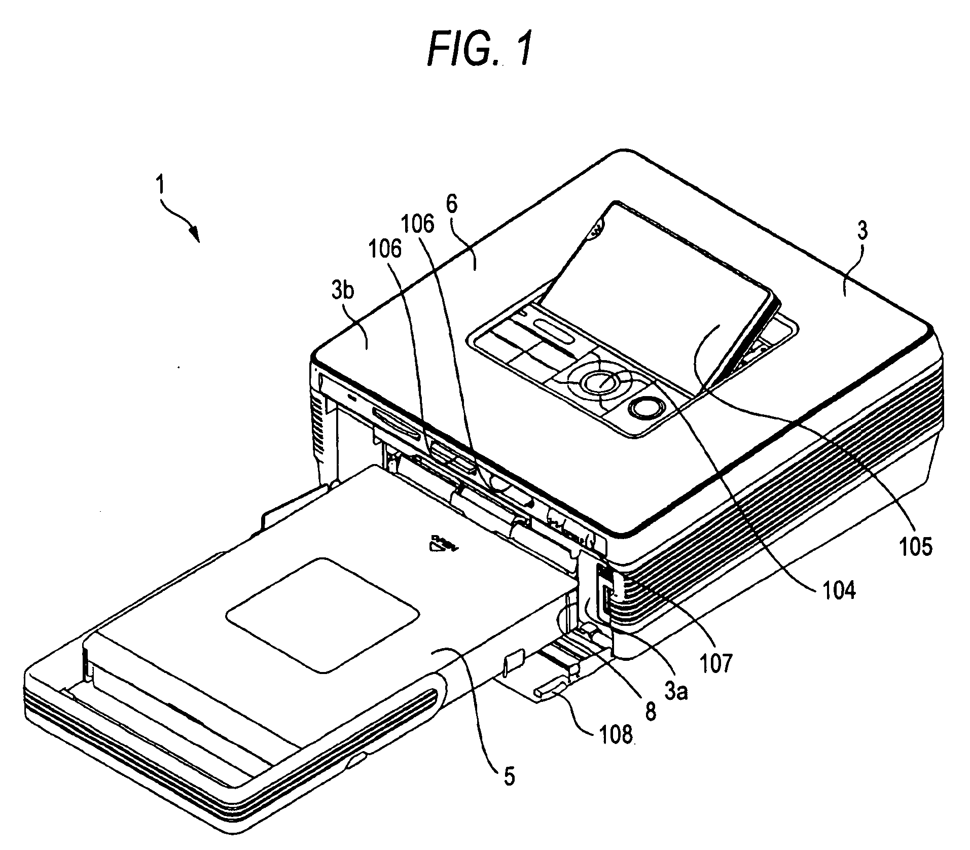
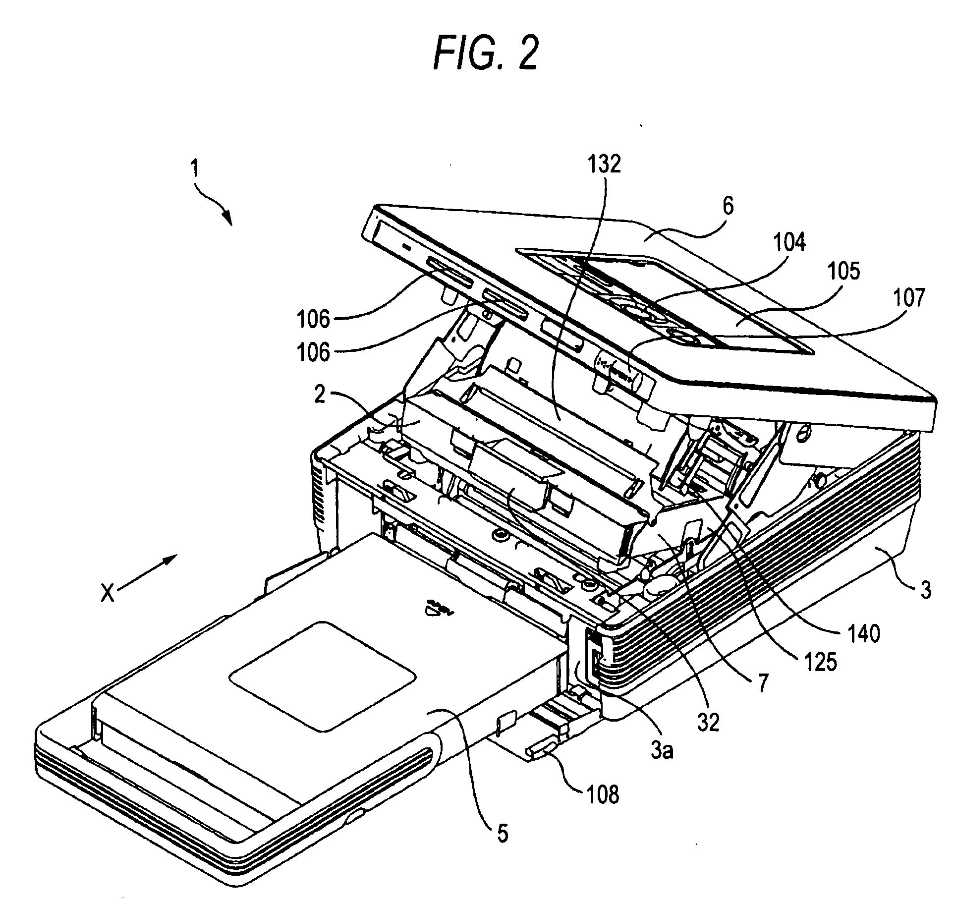
[0057] In the below, by referring to the accompanying drawings, described in detail is an ink ribbon cartridge to which the invention is applied and a printer device using the ink ribbon cartridge. This printer device 1 is attached with an ink ribbon cartridge 2, which carries therein an ink ribbon. The printer device 1 includes a thermal head, and a platen roller that is disposed at the position opposing the thermal head. Between the thermal head and the platen roller, an ink ribbon and a printing paper are made to run so that the ink ribbon receives the thermal energy from the thermal head. In this manner, the coloring material of the ink ribbon is thermally transferred to the printing paper so that the printing paper is printed with images. As shown in FIG. 1, the printer device 1 is provided with a device body 3 being substantially rectangular. The device body 3 is attached with the ink ribbon cartridge 2, and transfers, for printing, the printing paper from / to inside to / from ou...


PUM


Abstract

An ink ribbon cartridge to be inserted to and removed from a printer device that prints an image to a printing medium by heating the printing medium with an ink ribbon closely attached thereto. The ink ribbon cartridge includes: a cartridge body provided with a pair of housing sections for housing, with a space therebetween, a pair of spools to be able to freely rotate for winding of the ink ribbon; and a pair of guide sections that are provided on both side surfaces in a direction orthogonal to an insertion / removal direction of the cartridge body, and serving as a guide for insertion to and removal from an ink ribbon cartridge holder provided to the printer device through support by a guide support section formed to the ink ribbon cartridge holder with a cross section of a substantially square bracket shape.

Description

CROSS REFERENCES TO RELATED APPLICATIONS [0001] The present invention contains subject matter related to Japanese Patent Application JP 2006-057011 filed in the Japanese Patent Office on Mar. 2, 2006, the entire contents of which being incorporated herein by reference. BACKGROUND OF THE INVENTION [0002] 1. Field of the Invention [0003] The present invention relates to an ink-ribbon-housing ink ribbon cartridge, and a printer device that includes therein the ink ribbon cartridge, and using a thermal head, thermally transfers the color material of the ink ribbon to a printing medium. [0004] 2. Description of the Related Art [0005] A printer device for printing images and characters to a printing medium is typified by a printer device of thermal transfer type. With such a printer device, a color material of an ink layer formed to one surface of an ink ribbon is sublimed, and the color material is thermally transferred to a printing medium so that color images and characters are printed...

Claims


Application Information

Patent Timeline
Patent Type & Authority Applications(United States)
IPC IPC(8): B41J35/28
CPCB41J17/32B41J32/00B41J33/12
Inventor OTA, SHUICHIKUSHIRO, SUNAOYANBE, ATSUSHIYONEOKA, HIDEKINUMATA, KOICHIMURATA, KAZUYOSHIKATSUNO, HIROSHI
Owner SONY CORP
Why Eureka
Try Eureka