Method for optimizing valve position and pump speed in a PID control valve system without the use of external signals

pump speed technology, applied in the field of pumps, can solve the problems of not cannot seeking an optimal pump speed and cannot seek an optimal speed and control valve position from a pid control valve system, so as to achieve the effect of optimizing the valve position

Inactive Publication Date: 2007-09-13
ITT MFG ENTERPRISES LLC
View PDF18 Cites 70 Cited by
  • Summary
  • Abstract
  • Description
  • Claims
  • Application Information

AI Technical Summary

Benefits of technology

[0011] In effect, the present invention will overcome shortcomings of the above-mentioned prior art devices for pumping systems that utilize PID control valve logic to control the process where the input of valve data / position or other external signals is not desirable. The algorithm according to the present invention utilizes flow reference data which can be mathematically determined as a function of the various pump and motor parameters such as speed, torque or power or from calibrated flow curves stored in the evaluation device, or from the external flow reference such as a flowmeter.
[0012] Embodiments of the present invention may include one or more of the following features: Once the PID control valve has reached its steady state normal condition, a calculated flow value may be captured and compared to the current flow value obtained after the variable frequency drive has decreased in frequency (speed). For pressure control applications, the valve position may be optimized if the current flow is within 90-110% of the pump best efficiency flow at current speed. A final check may be made for a wide open control valve condition by increasing pump speed a set amount and comparing the current flow value to a saved flow value, and if there is no increase in flow the valve position is optimized. If the controller has already reached its optimized state, and if either the actual motor torque increases by 5% or greater, or the actual flow increases by 5% or greater for longer than the delay period, the valve optimization process may be restarted at maximum speed. Alternatively, if the controller has already reached its optimized state, and if either the actual motor torque decreases by 5% or more, or the actual flow decreases by 5% or more, the valve optimization process may be restarted at the current operating point. A secondary user selectable wide open valve check may be made if a change in actual motor torque is 2% or more but less than 5% of the optimized state for the response delay period, and if this condition is true and the actual flow is greater than the optimized flow value after a speed increment change, the optimization process may be restarted at maximum speed. Moreover, the valve position may be optimized just prior to the speed threshold where the flow condition of the algorithm is no longer true, or just prior to reaching minimum speed if the flow condition remains true, alone or together with one or more of the aforementioned features.

Problems solved by technology

However, while this technique can monitor pump power and differential pressure data to predict flow from a calibrated pump curve at various speeds, it cannot seek an optimal pump speed and valve position from a PID control valve system.
While this technique can monitor the relationship of torque and speed versus pump flow rate and has the ability to regulate pump flow by using a variable frequency drive (VFD) to adjust centrifugal pump speed, it cannot seek an optimal pump speed and valve position from a PID control valve system.
While this technique can regulate flow or pressure via a PID control loop embedded in a variable frequency drive (VFD) by using feedback from an external transmitter, it cannot seek an optimal speed and control valve position from a PID control valve system.

Method used


Image

  • Method for optimizing valve position and pump speed in a PID control valve system without the use of external signals
  • Method for optimizing valve position and pump speed in a PID control valve system without the use of external signals
  • Method for optimizing valve position and pump speed in a PID control valve system without the use of external signals

Examples


Embodiment Construction

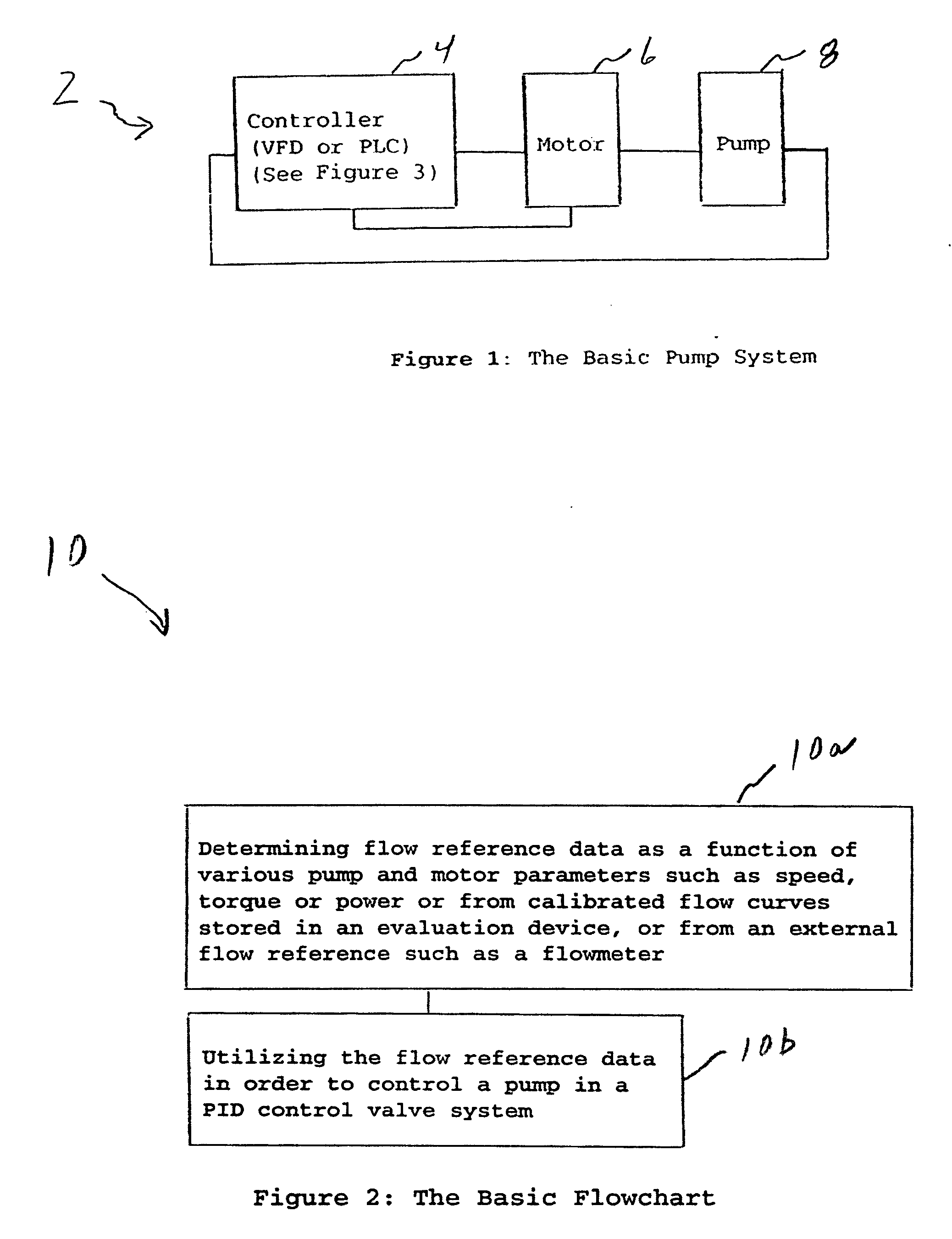
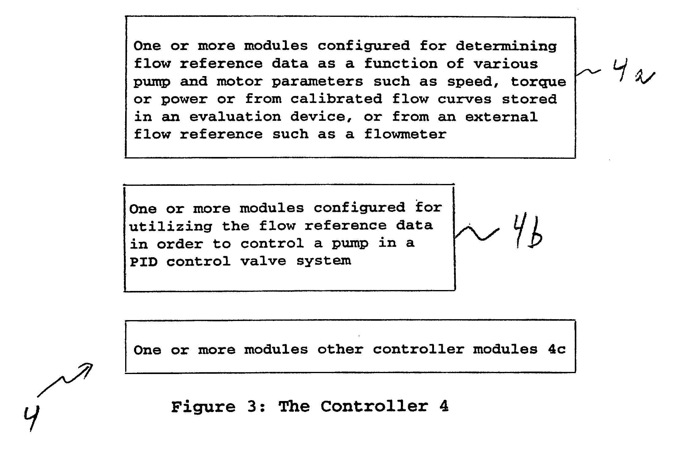
[0018]FIG. 1 shows the basic pump system generally indicated as 2 according to the present invention, having a controller 4, a motor 6 and a pump 8. In operation, and according to the present invention, the controller 4 provides for determining flow reference data as a function of various pump and motor parameters such as speed, torque or power or from calibrated flow curves stored in an evaluation device (not shown), or from an external flow reference such as a flowmeter (not shown); and for utilizing the flow reference data in order to control the pump 8, consistent with that shown and described herein.

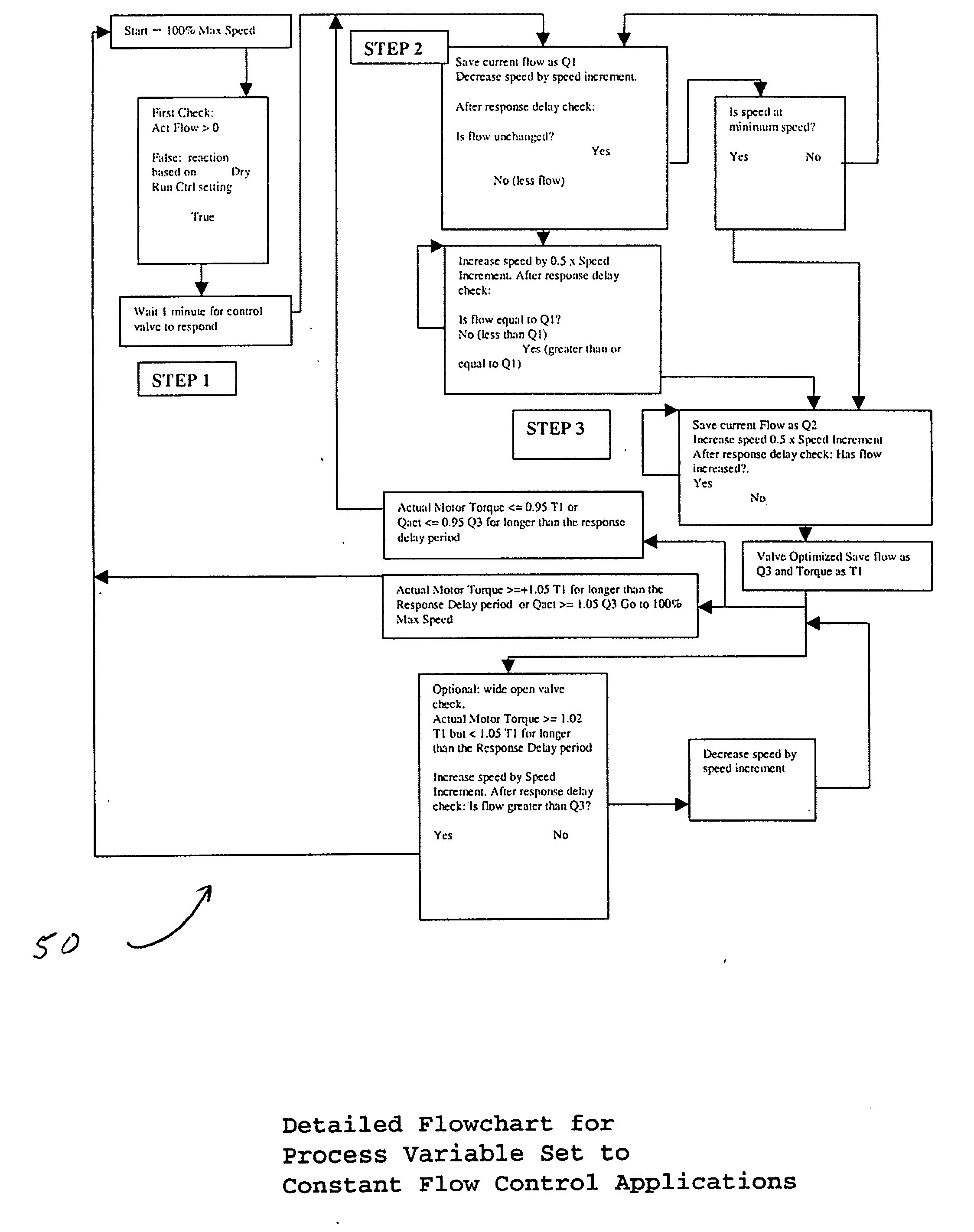
[0019]FIG. 2 shows, by way of example, a flowchart generally indicated as 10 having the basic steps 10a and 10b, of the pump flow determination algorithm that may be implemented by the controller 4 according to the present invention. The determined flow value may also be used as an input to a PID control loop to control flow without an external flowmeter or traditional instrumentat...


PUM


Abstract

The present invention provides an algorithm that utilizes flow reference data which can be mathematically determined as a function of various pump and motor parameters such as speed, torque or power or from calibrated flow curves stored in an evaluation device, or from an external flow reference such as a flowmeter. Once the PID control valve has reached its steady state condition a calculated flow value is captured and compared to the current flow value obtained after the variable frequency drive has decreased in frequency (speed). The valve position is optimized just prior to the speed threshold where the flow condition of the algorithm is no longer true.

Description

CROSS-REFERENCE TO RELATED APPLICATIONS [0001] This application claims benefit to provisional patent application Ser. No. 60 / 780,547, filed on 8 Mar. 2006, which is hereby incorporated by reference in its entirety. [0002] The application is also related to and claims benefit to patent application Ser. No. 11 / 636,355 (05GI003US / 911-2.24-2), filed Dec. 8, 2006, entitled “Method for determining pump flow without the use of traditional sensors,” as well as patent application Ser. No. file no. 11 / 601,373 (05GI002 / 911-2.22-2), entitled “Method and Apparatus for Pump Protection Without the Use of Traditional Sensors,” filed 17 Nov. 2006, which are also both hereby incorporated by reference in their entirety.BACKGROUND OF THE INVENTION [0003] 1. Field of the Invention [0004] The present invention relates to a pump, including a centrifugal pump; and more particularly to a method and apparatus for optimizing valve position and pump speed in a PID control valve system without the use of extern...

Claims


Application Information

Patent Timeline
Patent Type & Authority Applications(United States)
IPC IPC(8): F04B49/00
CPCF04D15/0022F04D15/0088F04D15/0066
Inventor STAVALE, ANTHONY E.VERDEHEM, BRIAN S.
Owner ITT MFG ENTERPRISES LLC
Why Eureka
Try Eureka