Wireless communication handoffs within a macrocell

a macrocell and wireless communication technology, applied in the field of communication, can solve the problems of pilot pollution, scrambling code assignment, and inability of outside bts equipment to provide adequate radio frequency coverage, and achieve the effect of facilitating handoffs and reducing the number of cell definition codes required

Inactive Publication Date: 2007-09-13
LUCENT TECH INC
View PDF9 Cites 56 Cited by
  • Summary
  • Abstract
  • Description
  • Claims
  • Application Information

AI Technical Summary

Benefits of technology

[0020] One advantage to such an arrangement is that it greatly reduces the number of cell definition codes required for a neighbor list. In one example, a

Problems solved by technology

One reason for doing so is that outside BTS equipment may not be able to provide adequate radio frequency (RF) coverage to provide reliable wireless service throughout the interior of a building.
Including BTS equipment to establish microcells such as within buildings introduces challenges and complexities associated with managing handoffs between the macrocell and the microcell BTSs, for example.
The problems associated with handoffs between a macrocell and microcells within the macrocell include pilot pollution, neighbor list resource exhaustion, pseudo random noise offset (PN offset) assignment, scrambling code assignment and traffic capacity loss.
Pilot pollution arises from the RF of the outside macrocell undesirably leaking inside a building or otherwise within an area considered a microcell served by a separate BTS.
The outside macrocell RF in this regard essentially pollutes the inside as the RF leakage interferes with the inside RF.
At the same time, making an in-building or microcell system too powerful results in RF from the inside system leaking outside of the microcell.
This can cause problems with macrocell performance, also.
Because every in-building BTS must be on the macrocell's neighbor list, problems arise where there are more than a few such BTSs.
Adding a plurality of in-building BTSs to a neighbor list becomes problematic.
A drawback to increasing the neighbor list size is that it slows down a mobile stat

Method used


Image

  • Wireless communication handoffs within a macrocell
  • Wireless communication handoffs within a macrocell
  • Wireless communication handoffs within a macrocell

Examples


Embodiment Construction

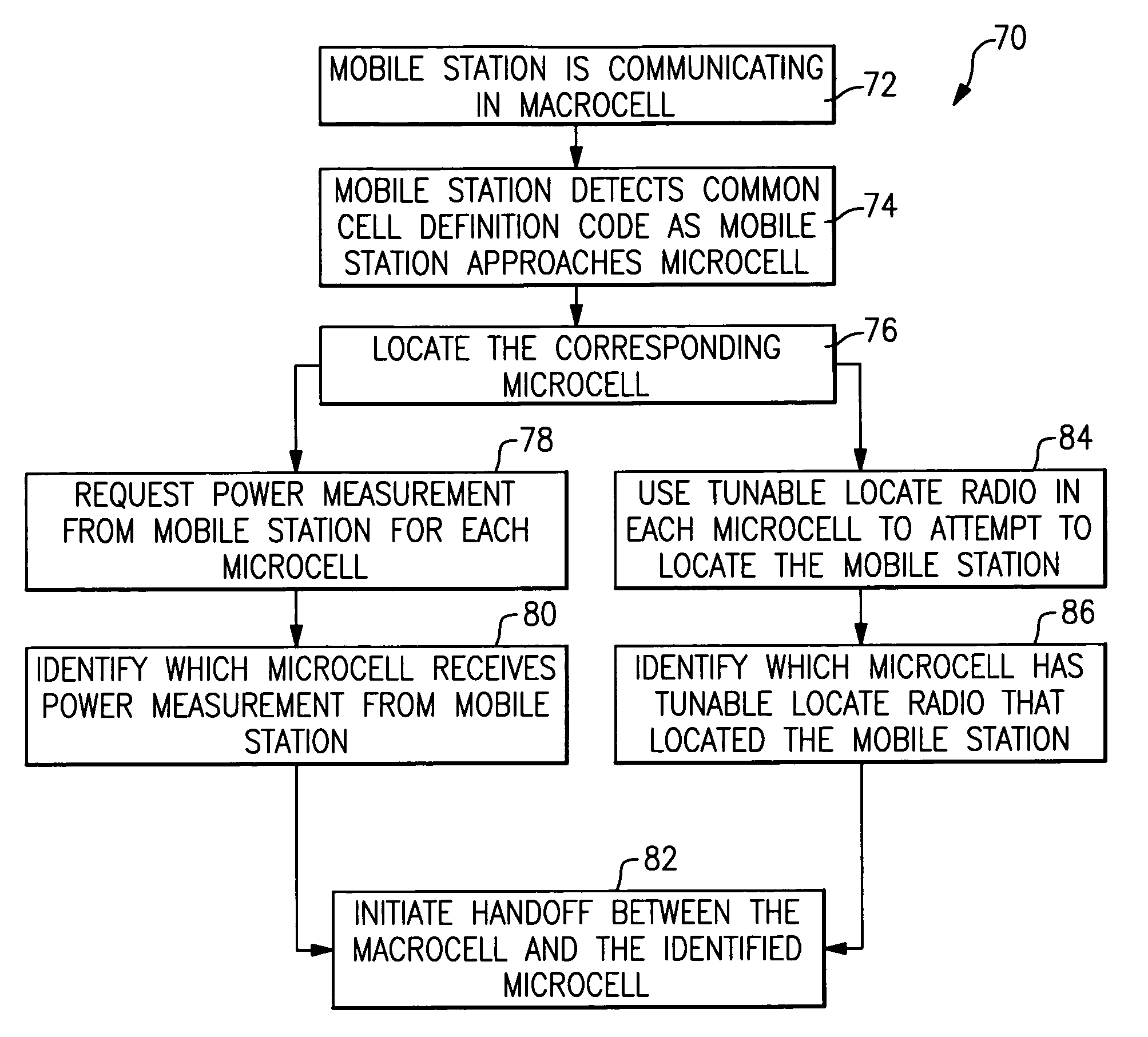
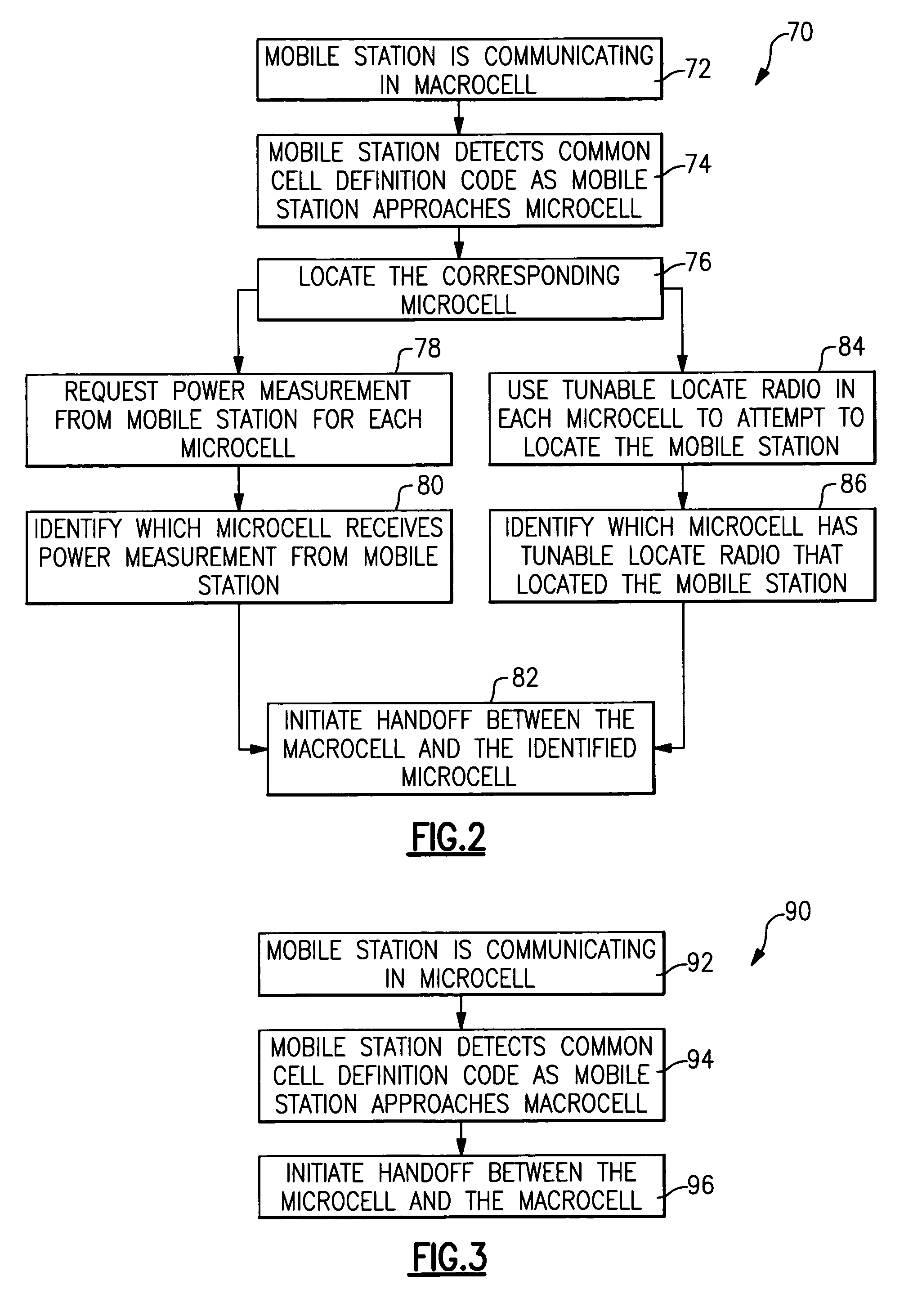
[0027] This invention includes a unique strategy for triggering handoff between a macrocell and any one of a plurality of microcells such as in-building cells within the macrocell coverage area. A disclosed example includes using a common cell definition code for each of a plurality of microcells within a microcell coverage area. One common cell definition code is used for triggering handoffs from the macrocell to a microcell. Another common cell definition code is used for triggering all handoffs from a microcell to the macrocell. Techniques for locating the mobile station provide sufficient identity of the microcell involved in a handoff as a mobile station enters the microcell coverage area.

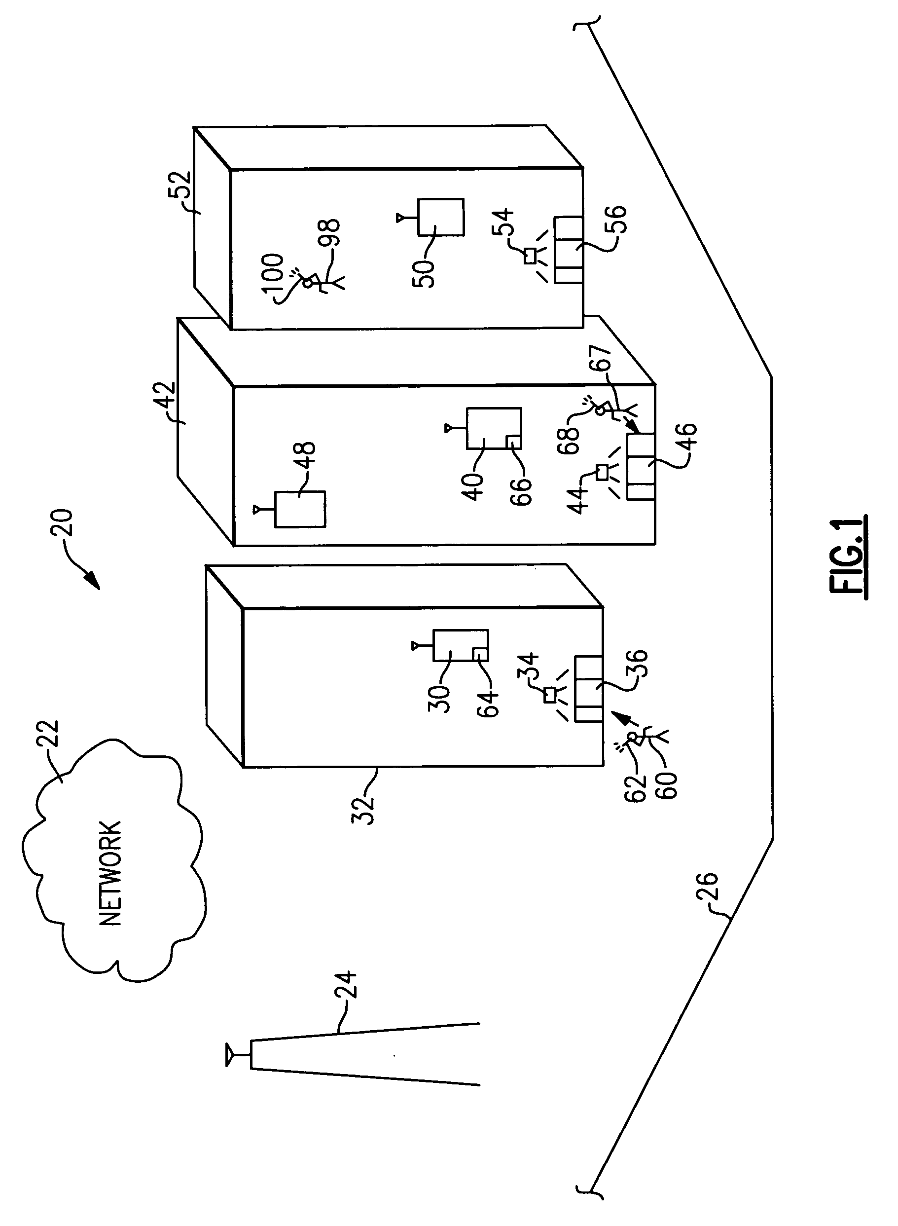
[0028]FIG. 1 schematically shows selected portions of a wireless communication system 20. A wireless network 22 includes known elements and operates in a known fashion to facilitate wireless communications. In the illustration, a base station transceiver (BTS) 24 and an associated radio tower...


PUM


Abstract

Handoffs within a wireless communication system (20) include using a common cell definition code for each of a plurality of microcell BTSs (30, 40, 50) to facilitate handoffs between a macrocell (26) and any one of the microcells. In a disclosed example, a common cell definition code such as a PN offset or a scrambling code is used to trigger a handoff from the macrocell (26) to any one of the microcell BTSs (30, 40, 50). A mobile station locate feature identifies which of the BTSs is involved in the handoff. Another common cell definition code is used in one example to trigger all handoffs from any one of the microcells (30, 40, 50) to the macrocell (26). Soft handoff and hard handoff examples are disclosed.

Description

FIELD OF THE INVENTION [0001] This invention generally relates to communication. More particularly, this invention relates to wireless communications. DESCRIPTION OF THE RELATED ART [0002] Wireless communication systems are well known and in widespread use. Many systems are arranged to provide wireless service or coverage within geographically or otherwise distinct areas. Most systems include a plurality of base station transceivers (BTS) that are situated to provide coverage over particular areas. The area of coverage for each BTS is commonly referred to as a cell. As known, many cells are divided into several sectors to increase wireless coverage within the cell. [0003] In some situations, a cell can be considered a macrocell because there are other BTS units within the macrocell region that are intended to serve a particular portion of the macrocell. These smaller areas within a macrocell can be referred to as microcells. One example use of a BTS to establish a microcell is to in...

Claims


Application Information

Patent Timeline
IPC IPC(8): H04Q7/20H04W36/04
CPCH04W36/04H04W36/0055H04W36/08H04W24/02H04W28/06
Inventor LI, PATRICKPAN, VICROSSETTI, DAVID A.
Owner LUCENT TECH INC
Why Eureka
Try Eureka