Shock-absorbing intervertebral implant

a technology of intervertebral implants and shock absorption, which is applied in the field of intervertebral implants, can solve the problems of nerve roots being trapped, two vertebrae separated by the disk to move abnormally towards each other, and the person affected by this problem to experience pain

Inactive Publication Date: 2007-09-13
ZIMMER SPINE INC
View PDF13 Cites 79 Cited by
  • Summary
  • Abstract
  • Description
  • Claims
  • Application Information

AI Technical Summary

Benefits of technology

[0009] a connection piece made of a second material of greater elastic deformability than said first material, said connection piece interconnecting said second ends of said two elements so that the stresses that are exerted on said two elements are damped, and said connection piece enabling said intervertebral implant to limit and brake the relative movements of said vertebrae.
[0020] As a result, the clips are easily fixed onto the wings of said elements once the spacer has been inserted. As explained in greater detail below, in this particular embodiment, since the wings are disengaged, the spacer is inserted without major surgery on the posterior ligaments.

Problems solved by technology

In particular, when the posterior portion of an intervertebral disk has deteriorated, extension of the spine causes the two vertebrae that are separated by the disk to move towards each other abnormally.
This generally causes the nerve roots to become trapped and causes the person who is affected by this problem to experience pain.
Such implants limit the extent to which the vertebrae can move towards each other since, when the spine is in extension, the spinous processes tend to come into abutment against the bottoms of the opposite notches in which they are inserted.
However, the material of which the spacer is made is hard compared with the material of an intervertebral disk which, when it is intact, limits the extent to which the vertebrae can move towards each other, so much so that the jolts which can be transmitted to the spine, e.g. while walking, are not damped between two vertebrae interconnected by a spacer.
Furthermore, since the spacer does not have the same mechanical properties as the remaining portion of the intervertebral disk, the overall mechanical properties of the spine present significant discontinuities compared with an intact spine, thereby increasing deterioration of the intervertebral disk.

Method used


Image

  • Shock-absorbing intervertebral implant
  • Shock-absorbing intervertebral implant
  • Shock-absorbing intervertebral implant

Examples


Embodiment Construction

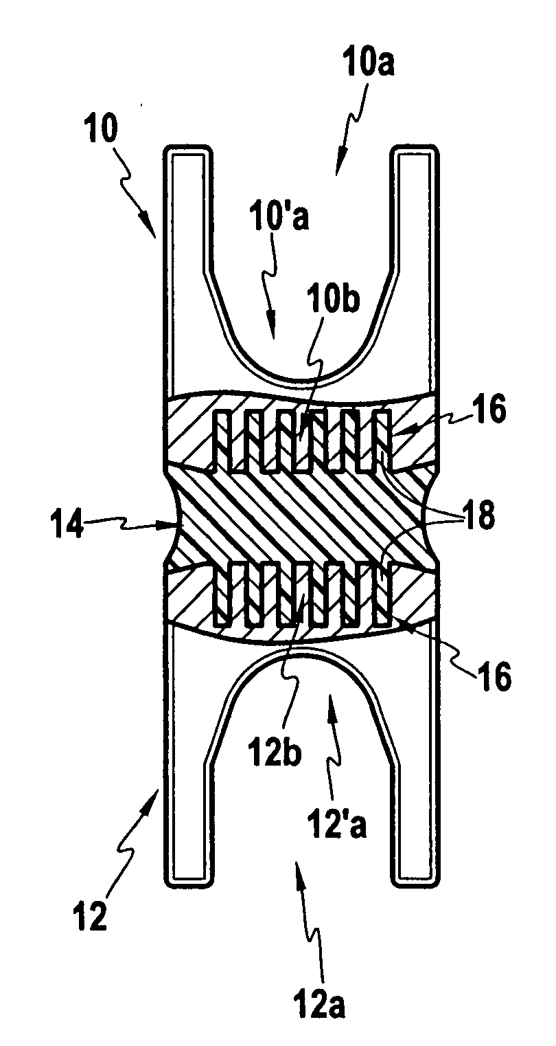
[0027] The spacer and the method of connecting the elements that constitute it are described initially with reference to FIG. 1.

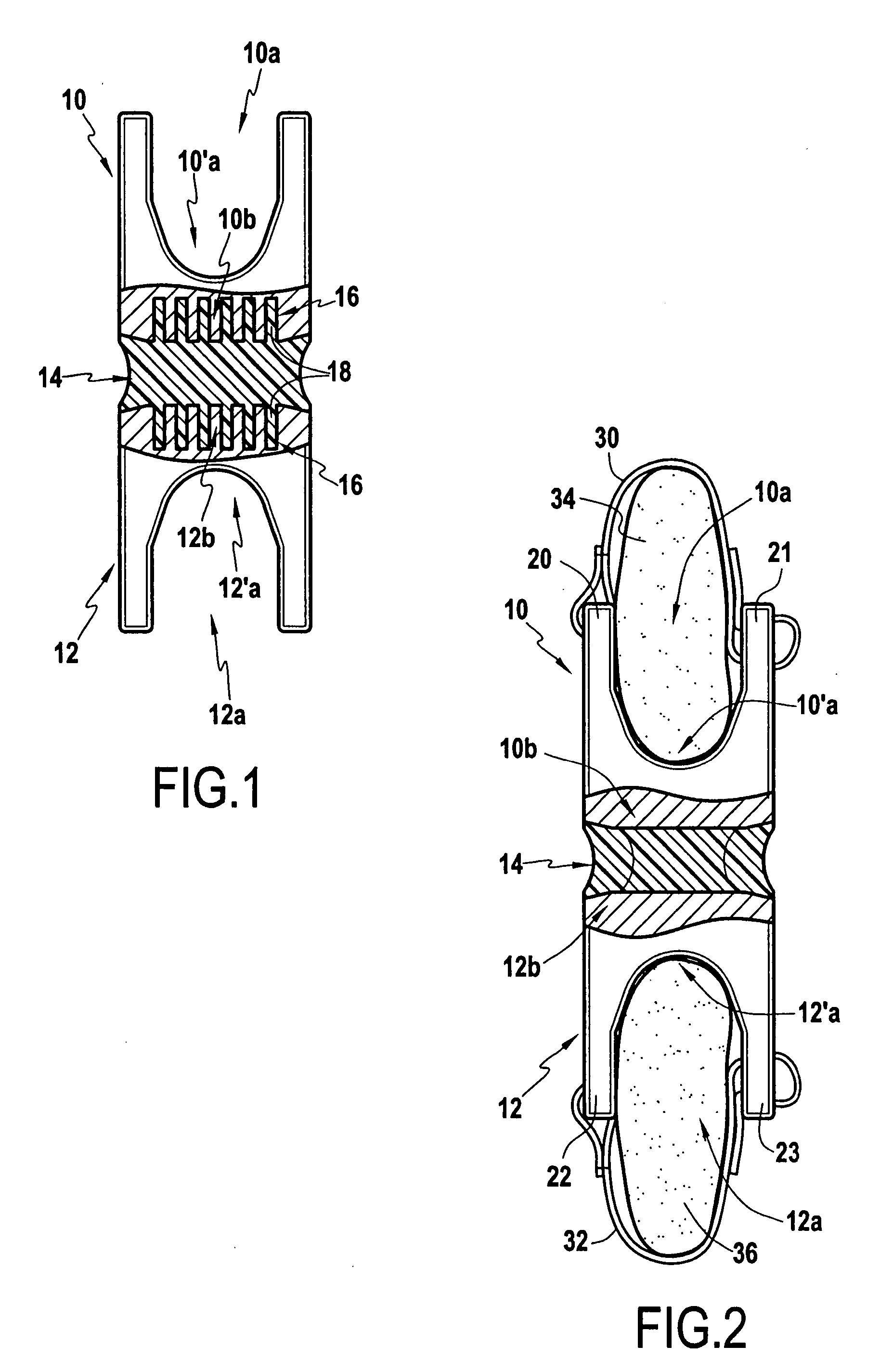
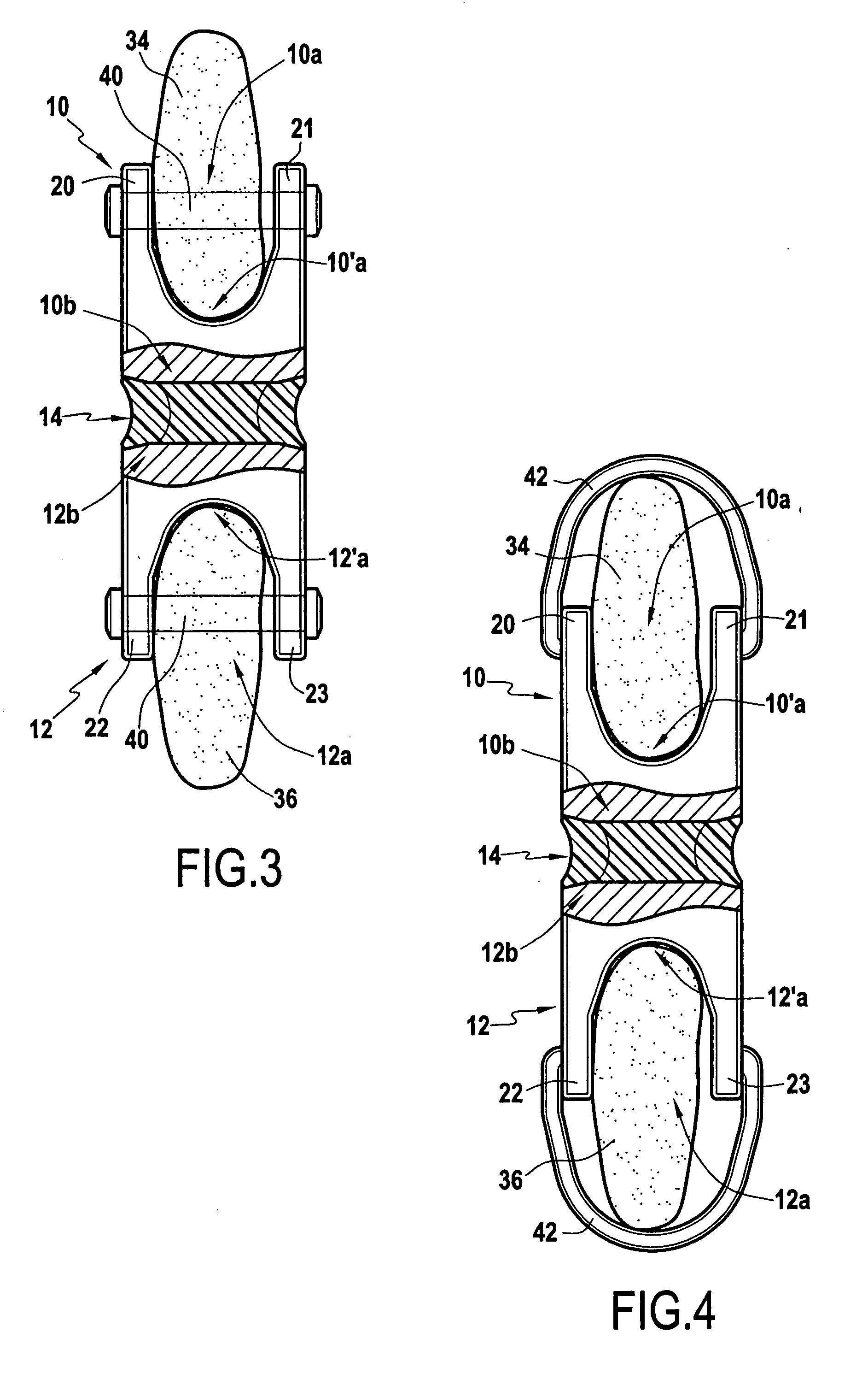
[0028] The intervertebral implant includes two symmetrical elements 10 and 12 each presenting a first end 10a and 12a and a second end 10b and 12b. The two elements 10 and 12 are made of a bio-compatible material of the titanium-alloy type, suitable for remaining permanently inside the body on the spine.

[0029] Each first end 10a, 12a presents a notch 10′a, 12′a in which a spinous process is capable of bearing in such a manner that each first end 10a, 12a surrounds substantially half of the circumference of a process, said process passing through the first end 10a, 12a.

[0030] The elements 10 and 12 are interconnected by a connection piece 14, interposed between them, in such a manner that said elements 10 and 12 are held symmetrically relative to each other. More precisely, it is the two ends 10b and 12b of the elements 10 and 12 that are interconnected. ...


PUM

PropertyMeasurementUnit
elastic deformabilityaaaaaaaaaa
lengthaaaaaaaaaa
mechanical propertiesaaaaaaaaaa

Abstract

The invention relates to an intervertebral implant comprising a spacer designed to be applied between two spinous processes of two vertebrae. The spacer comprises: two elements (10, 12) made of a first material, and each presenting a first end (10a, 12a) and a second end (10b, 12b), said first end (10a, 12a) being securable to a spinous process; and a connection piece (14) made of a second material of greater elastic deformability than said first material, said connection piece interconnecting said second ends (10b, 12b) of said two elements (10, 12) so that the stresses that are exerted on said two elements (10, 12) are damped, and said connection piece enabling said intervertebral implant to limit and brake the relative movements of said vertebrae.

Description

[0001] This Application is a continuation of U.S. application Ser. No. 10 / 332,412 filed on Jan. 7, 2003, which is a National Stage of PCT / FR01 / 02261 filed Jul. 12, 2001, which claims priority to French patent 00 09093 filed on Jul. 12, 2000.FIELD OF THE INVENTION [0002] The present invention relates to an intervertebral implant designed to be applied, in particular, between two spinous processes of two vertebrae. BACKGROUND OF THE INVENTION [0003] The indications for which this type of implant is inserted and fixed between the spinous processes generally originate from deterioration of the intervertebral disk. In particular, when the posterior portion of an intervertebral disk has deteriorated, extension of the spine causes the two vertebrae that are separated by the disk to move towards each other abnormally. This generally causes the nerve roots to become trapped and causes the person who is affected by this problem to experience pain. [0004] Intervertebral implants comprising a s...

Claims


Application Information

Patent Timeline
Patent Type & Authority Applications(United States)
IPC IPC(8): A61F2/44A61B17/70A61L27/00A61B17/84A61B17/86A61F2/00A61F2/30
CPCA61B17/7062A61B17/842A61F2310/00023A61F2002/30563A61B17/86A61B17/7053A61F2/44
Inventor LE COUEDIC, REGISSENEGAS, JACQUES
Owner ZIMMER SPINE INC
Why Eureka
Try Eureka