Method and apparatus for screen printing

a screen printing and screen printing technology, applied in the direction of printing, printing apparatus, coating, etc., can solve the problems of deformation of the print pattern deformation of the screen mask, wet soldering etc., and achieve the effect of reducing the raising speed of the printed board, and preventing the blurred print pattern

Active Publication Date: 2007-09-20
FUJI MASCH MFG CO LTD
View PDF2 Cites 12 Cited by
  • Summary
  • Abstract
  • Description
  • Claims
  • Application Information

AI Technical Summary

Benefits of technology

[0011]As the result of the above-described construction, the screen mask is held between the squeegee and the mask support plate thereby to be held therebetween before the printed board is brought into contact with the underside of the screen mask. Accordingly, the screen mask can be prevented from minute vibration, whereupon the print pattern can effectively be prevented from being blurred in the re-printing.
[0012]Furthermore, when the mask support plate located at the side of the printed board is raised into contact with the underside of the screen mask in the re-print, the mask support plate and the printed board are raised so that the mask support plate is brought into contact with the underside of the screen mask while the mask support plate is located higher by a predetermined dimension than the printed board, and subsequently, the raising speed of the printed board is reduced so that the printed board is brought into contact with the underside of the screen mask more slowly.
[0013]Consequently, it is rendered easier to

Problems solved by technology

Defective printing occurs for some cause even when a normal print pattern is obtained by a single time of screen printing.
In the re-printing, however

Method used


Image

  • Method and apparatus for screen printing
  • Method and apparatus for screen printing
  • Method and apparatus for screen printing

Examples


Embodiment Construction

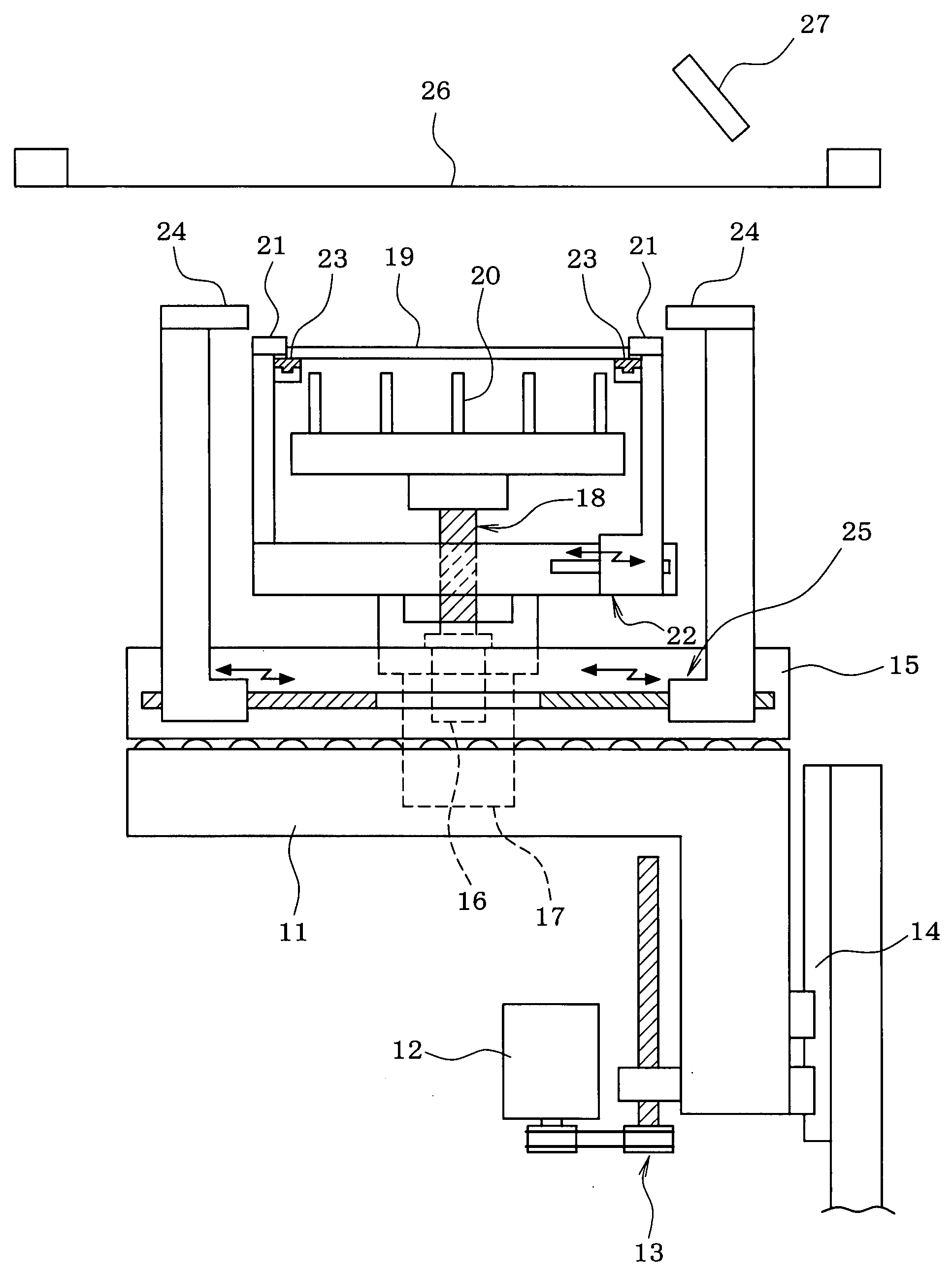
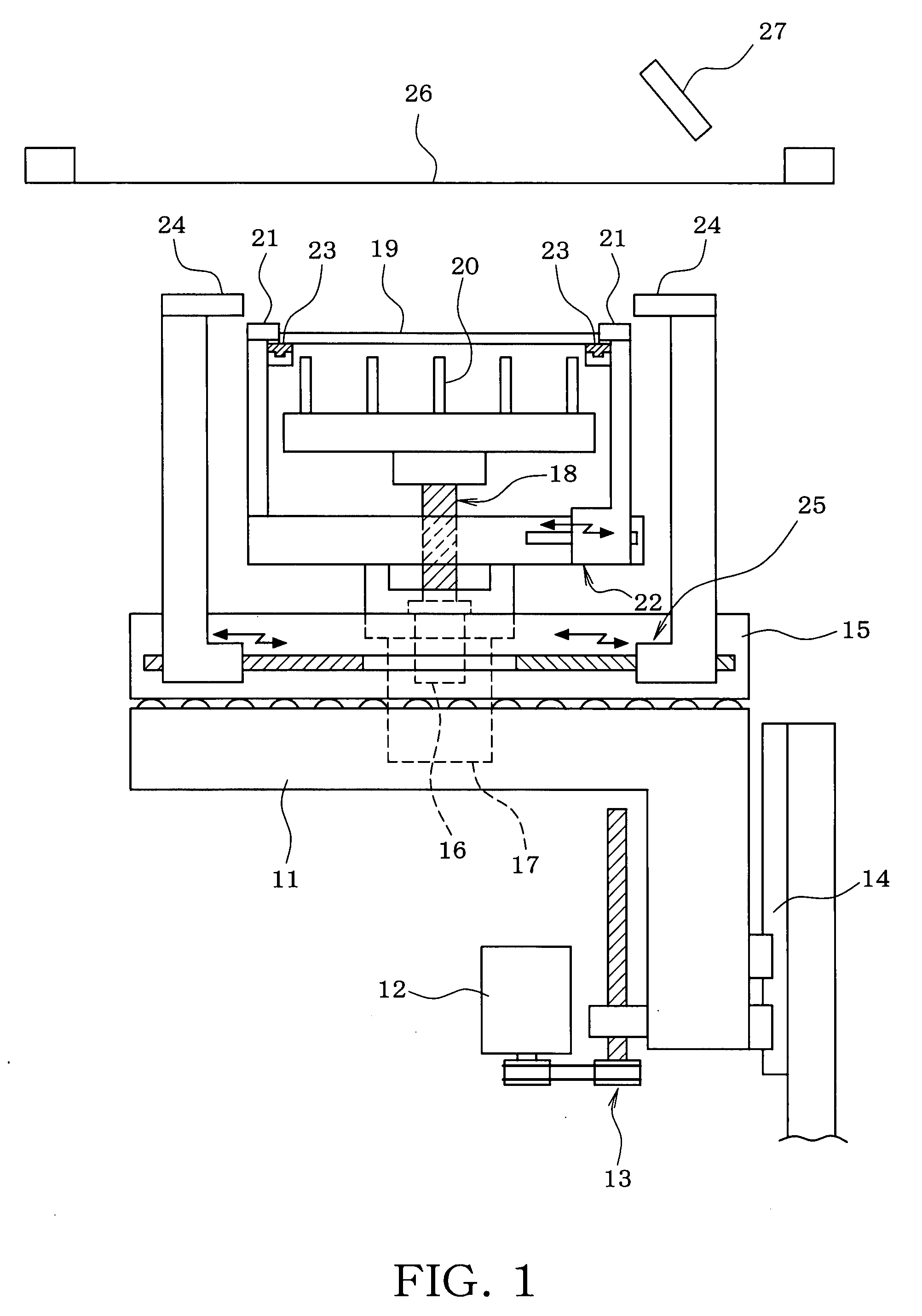
[0020]One embodiment of the present invention will be described in detail. Firstly, the construction of the screen-printing apparatus will be described with reference to FIG. 1. The screen-printing apparatus includes a lifting table 11 slid vertically (in the Z-direction) along a lifting guide 14. The lifting table 11 is driven by a Z1-axis feed screw mechanism 13 which is further driven by a Z1-axis motor 12. The lifting table 11 includes a base 15 whose position is adjustable in the X-Y direction and a θ-direction. A Z2-axis motor 16 and a Z3-axis motor 17 are fixed to the base 15. The Z2-axis motor 16 drives a Z2-axis feed screw mechanism 18 so that a plurality of back-support pins 20 receiving and supporting the circuit board 19 from below are lifted up and down.

[0021]The Z3-axis motor 17 drives a Z3-axis feed screw mechanism (not shown) so that two side dampers 21 clamping both side edges of the circuit board 19 respectively are lifted up and down. A clearance between the side ...


PUM


Abstract

When a printed circuit board is inspected and determined to have an insufficient amount of printing of a print pattern, the printed board is returned to a screen-printing apparatus so that a new print pattern is formed so as to overlap a previous print pattern. In the re-printing, a raising speed of the printed board at a final stage of the board raising operation is rendered lower than in the previous screen printing so that the printed board is brought into contact with the underside of the screen mask more slowly.

Description

BACKGROUND OF THE INVENTION[0001]1. Field of the Invention[0002]The present invention relates to a screen-printing method in which a circuit board which has already been screen-printed is screen-printed again so that a new print pattern is formed on a previous pattern and a screen-printing apparatus carrying out the above-described method.[0003]2. Description of the Related Art[0004]Screen-printing apparatuses have generally been provided for screen-printing a solder pattern or the like on a circuit board. For example, JP-A-2000-956 discloses such a screen-printing apparatus in which a circuit board transferred below a screen mask is raised and held in contact with the underside of the screen mask. A squeegee brought into contact with an upper surface of the screen mask is moved so that the circuit board is screen-printed.[0005]Defective printing occurs for some cause even when a normal print pattern is obtained by a single time of screen printing. Upon occurrence of such defective ...

Claims


Application Information

Patent Timeline
IPC IPC(8): B41M1/12
CPCB41M1/12H05K3/1216H05K2203/163H05K3/3484H05K2203/1476H05K3/245H05K3/3485
Inventor MIZUNO, MANABUHIRUKAWA, RITSUO
Owner FUJI MASCH MFG CO LTD
Why Eureka
Try Eureka