Oil separator for blowby gas

a technology of oil separator and blowby gas, which is applied in the direction of crankcase ventillation, combustion engines, machines/engines, etc., can solve the problems of inevitably leakage of blowby gas containing a large amount of unburned hydrocarbons, and achieve the effect of prolonging the length of the common flow path section, avoiding unnecessary enlargement of the overall oil separator, and improving oil separation performan

Inactive Publication Date: 2007-09-20
KOJIMA PRESS IND CO LTD +2
View PDF13 Cites 45 Cited by
  • Summary
  • Abstract
  • Description
  • Claims
  • Application Information

AI Technical Summary

Benefits of technology

[0035]According to this feature, the oil that has been passed through the minimum width section of the restricted section is smoothly guided into the oil passage downstream section, and caused to flow inside the oil passage downstream section, and as a result is advantageously discharged from the oil discharge port. Also, as the gas flow passage downstream section extends in a different direction to the oil passage downstream section, the oil discharge port is advantageously located away from the gas outlet port, whereby the oil can be effectively prevented from being discharged from the gas outlet port.
[0036](4) The oil separator according to the above feature (3), wherein the gas flow passage downstream section extends in a direction that is opposite from the extending direction of the oil passage downstream section. According to this feature, the oil discharge port is located more sufficiently away from the gas outlet port, whereby the oil can be more effectively prevented from being discharged from the gas outlet port.
[0037](5) The oil separator according to any one of the above features (1) to (4), wherein the flow passage regulating means is formed from at least one plate-shaped rib stood so as to extend integrally upwards from the bottom of the common flow path section, at a mid point of the common flow path section, at one surface in the width direction, so that the flow of the blowby gas inside the common flow passage is partially blocked, and the at least one plate-shaped rib has a gradually increasing section, of which a width gradually increases towards the bottom of the common flow path section to restrict the width of the restricted portion of the common flow path section, so that the width of the restricted portion becomes gradually narrower towards the bottom of the common flow path section. According to this feature, within the common flow path section, the size of the locations where the flow restriction section is arranged, namely the section occupied by the restricted section, is made as small as possible. There can be advantageously avoided an extension of the length of the common flow path section caused by the arrangement or installation of the restricted section, whereby unnecessary enlargements of overall the oil sepa

Problems solved by technology

As is well known, in an internal combustion engine, such as an engine of a car, at the time of operating the engine, a blowby gas containing a large amount of unburned hydrocarbons inevitably leaks out from gaps between piston rings and cylinder walls to a

Method used


Image

  • Oil separator for blowby gas
  • Oil separator for blowby gas
  • Oil separator for blowby gas

Examples


Embodiment Construction

[0021]The present invention is preferably practiced in at least the following features.

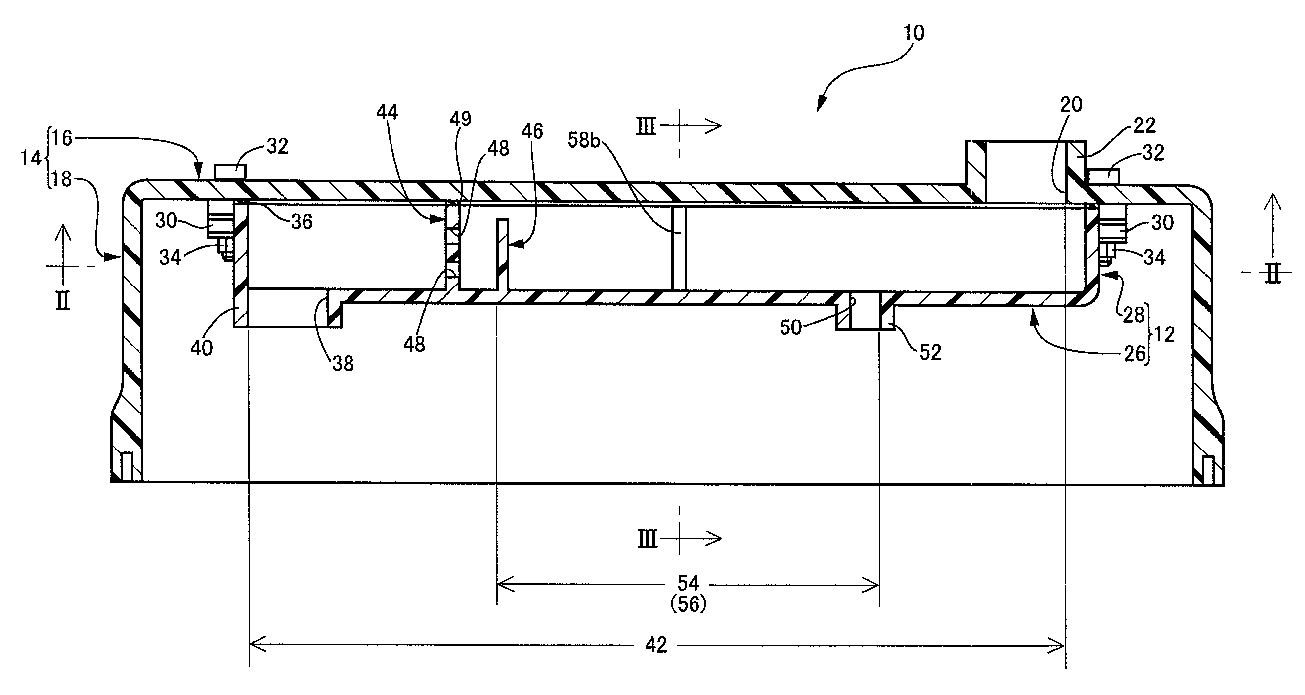
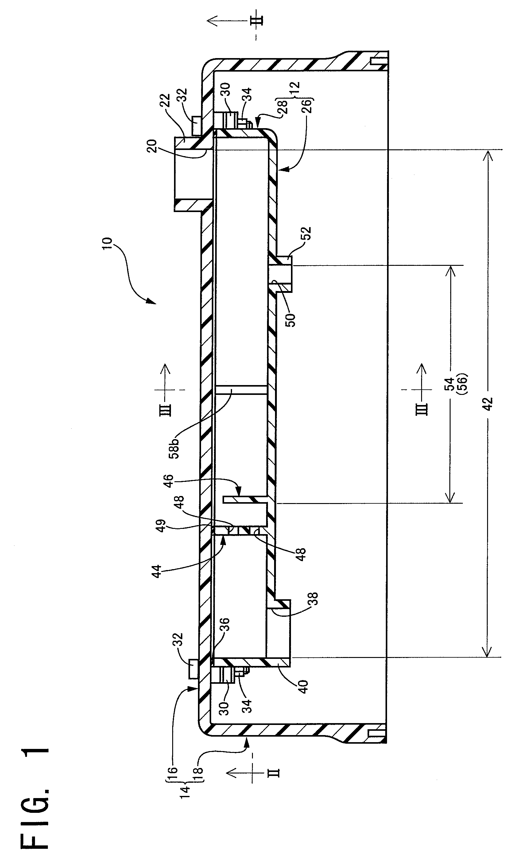
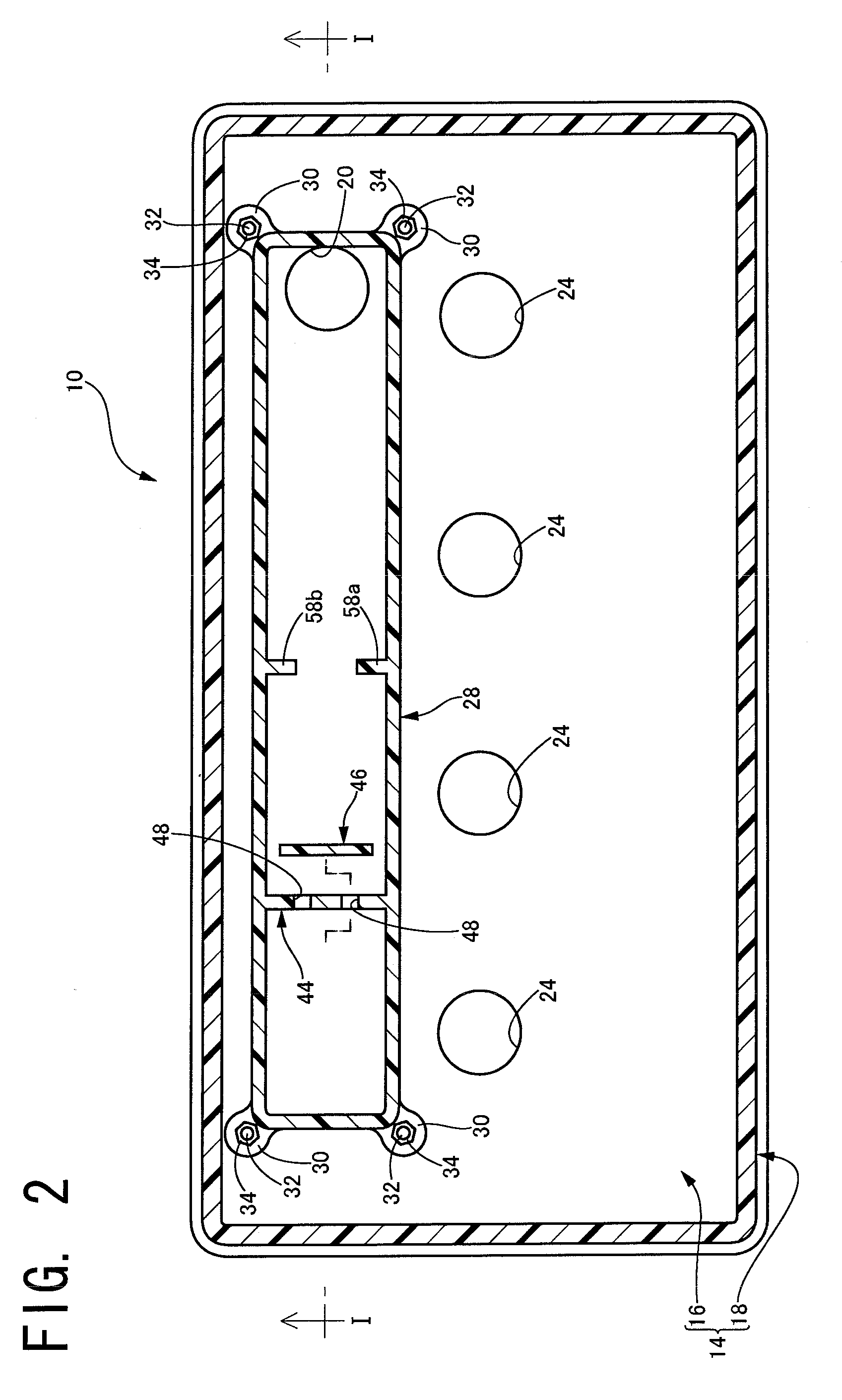
[0022](1) An oil separator for a blowby gas containing oil, comprising

[0023]a gas flow passage, provided with a gas inlet port and a gas outlet port for the blowby gas, for allowing a flow of the blowby gas from the gas inlet port towards the gas outlet port;

[0024]separation means, provided midway along the gas flow passage, for separating the oil from within the blowby gas which flows inside the gas flow passage;

[0025]an oil passage, at least a part of which is formed as a common flow path section located downstream of the separation means in the blowby gas flowing direction and shared by the gas flow passage, for allowing the oil separated by the separation means to flow along a bottom of the common flow path section; and

[0026]an oil discharge port, provided at a downstream side section, in the oil flowing direction, of the oil passage, for discharging the oil which flows inside the oil passage ...


PUM


Abstract

There is provided an oil separator for blowby gas exhibiting excellent oil separation performance in a stable manner. In a common flow path section of a gas flow passage in which the blowby gas flows and an oil passage provided with a bottom of the common flow path section where oil that has been separated from blowby gas by separation means provided midway along the gas flow passage, the width of a part of the common flow path section is regulated so as to become gradually smaller towards the bottom of the common flow path section, and a flow passage regulating section, for making part of the common flow path section that has the width regulated a restricted section, is provided so as to extend upwards from the bottom of the common flow path section.

Description

[0001]The present application is based on Japanese Patent Application No. 2006-075982 filed on Mar. 20, 2006, the contents of which are incorporated herein by reference.BACKGROUND OF THE INVENTION[0002]1. Field of the Invention[0003]The present invention relates to an oil separator for a blowby gas containing oil mist, and particularly relates to a novel structure of an oil separator for a blowby gas containing oil mist to separate the oil mist contained in the blowby gas generated inside an internal combustion engine.[0004]2. Discussion of Related Art[0005]As is well known, in an internal combustion engine, such as an engine of a car, at the time of operating the engine, a blowby gas containing a large amount of unburned hydrocarbons inevitably leaks out from gaps between piston rings and cylinder walls to an inside of a crankcase. As a result, in this type of vehicle engine, the blowby gas is often forcibly flowed inside an intake pipeline utilizing negative pressure inside the in...

Claims


Application Information

Patent Timeline
IPC IPC(8): F02B25/06
CPCF01M13/0416F01M2013/0461F01M2013/0433
Inventor YONEBAYASHI, MINORUTAKEUCHI, NOBUTAKAYASUHARA, SHIGEKIITO, KAORUTANAKA, TOSHIMITSU
Owner KOJIMA PRESS IND CO LTD
Why Eureka
Try Eureka