Display support mechanism

Inactive Publication Date: 2007-09-20
FUNAI ELECTRIC CO LTD
View PDF49 Cites 14 Cited by
  • Summary
  • Abstract
  • Description
  • Claims
  • Application Information

AI Technical Summary

Benefits of technology

[0023] According to the second aspect, further, the display support mechanism is provided with the stop member for inhibiting the platelike support shaft from coming off the display screen support member and the base support member, so that the stop member can easily hold a state of pressing the display screen support member and the base support member with the spring member. The display support mechanism is further provided with the plate member inserted into the platelike support shaft and arranged between the display screen support member and the stop member, whereby the stop member remains unsliding with respect to the display screen support member, to be inhibited from abrasion. Further, the stop member is provided in the form of the plate and receives the pressing force of the spring member on the end surface in the direction perpendicular to the thickness direction, whereby the stop member can receive the pressing force of the spring member with the strong end surface in the direction perpendicular to the thickness direction, to be inhibited from bending resulting from the pressing force of the spring member. In addition, the stop member can control the pressing force of the spring

Problems solved by technology

In the structure employing the round shaft as the axis of rotation for inclining the display screen by a prescribed angle disclosed in each of the patent documents such as the aforementioned Japanese Patent Laying-Open No. 2000-200048, however, grooving

Method used


Image

  • Display support mechanism
  • Display support mechanism
  • Display support mechanism

Examples


Embodiment Construction

[0045] An embodiment of the present invention is now described with reference to the drawings.

[0046] First, the structure of a display support mechanism 1 according to the embodiment of the present invention is described with reference to FIGS. 1 to 11.

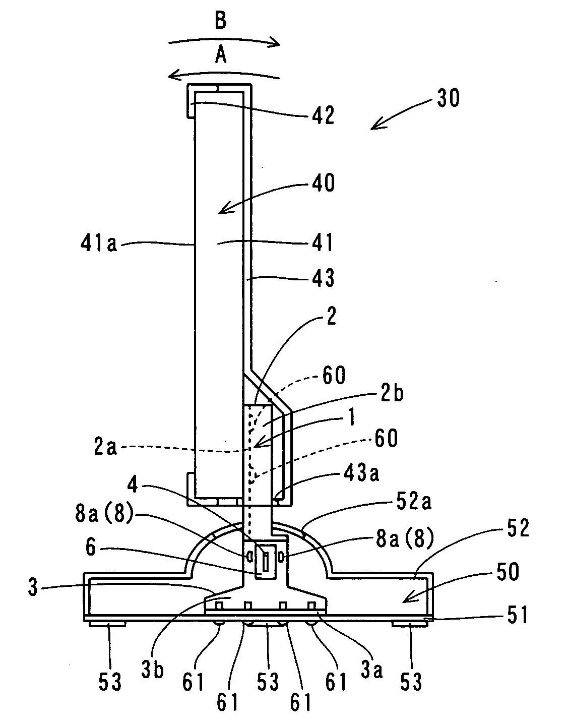
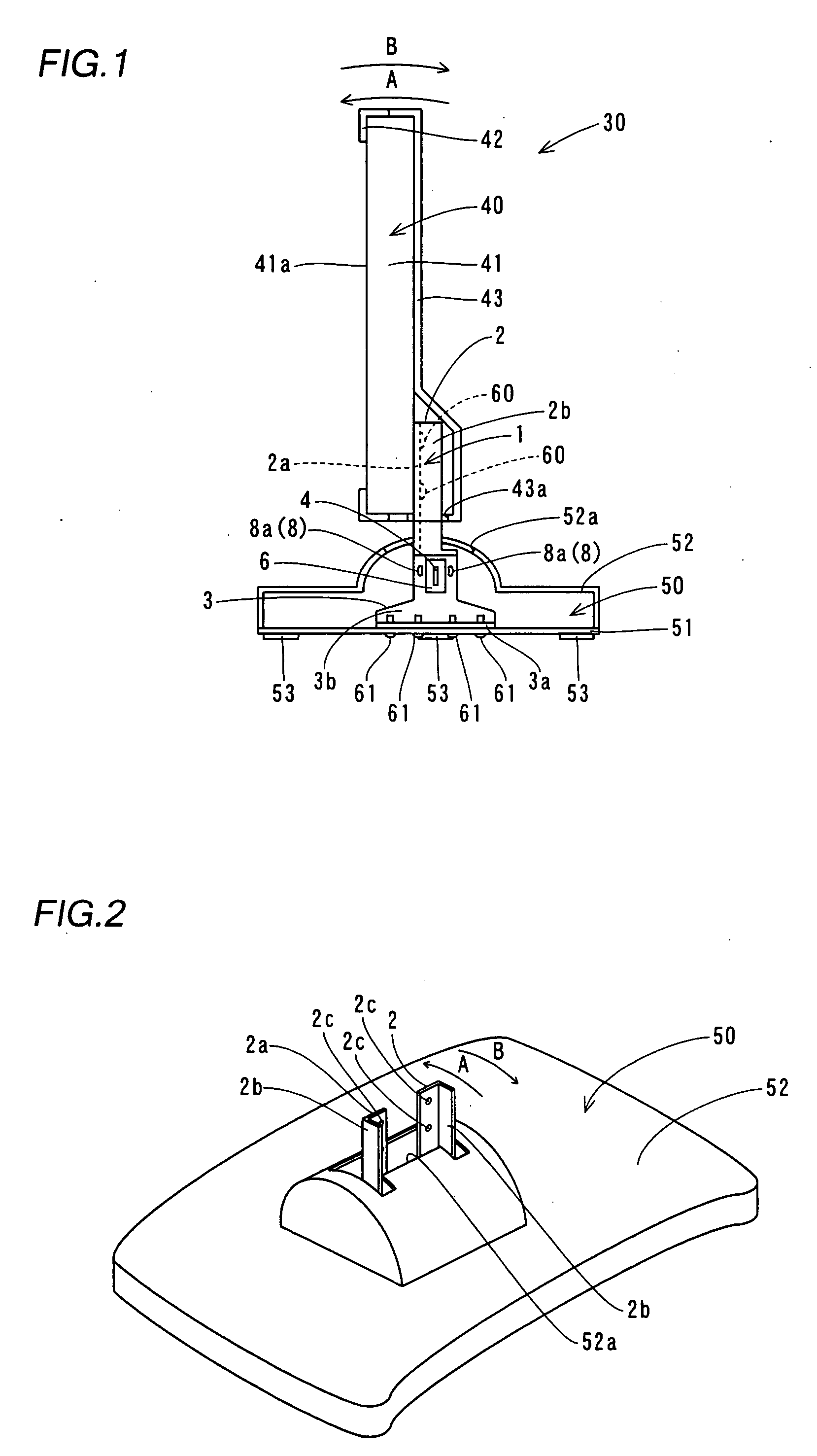
[0047] The display support mechanism 1 according to the embodiment of the present invention is provided for supporting a liquid crystal display portion 40 of a liquid crystal display 30, as shown in FIG. 1. This display support mechanism 1 is mounted on a base 50. The display support mechanism 1 supports the liquid crystal display portion 40 to be rotatable in directions A and B with respect to the base 50, as shown in FIGS. 1 and 2. The display support mechanism 1 is enabled to support the liquid crystal display portion 40 in a state inclined by a prescribed angle with respect to the base 50.

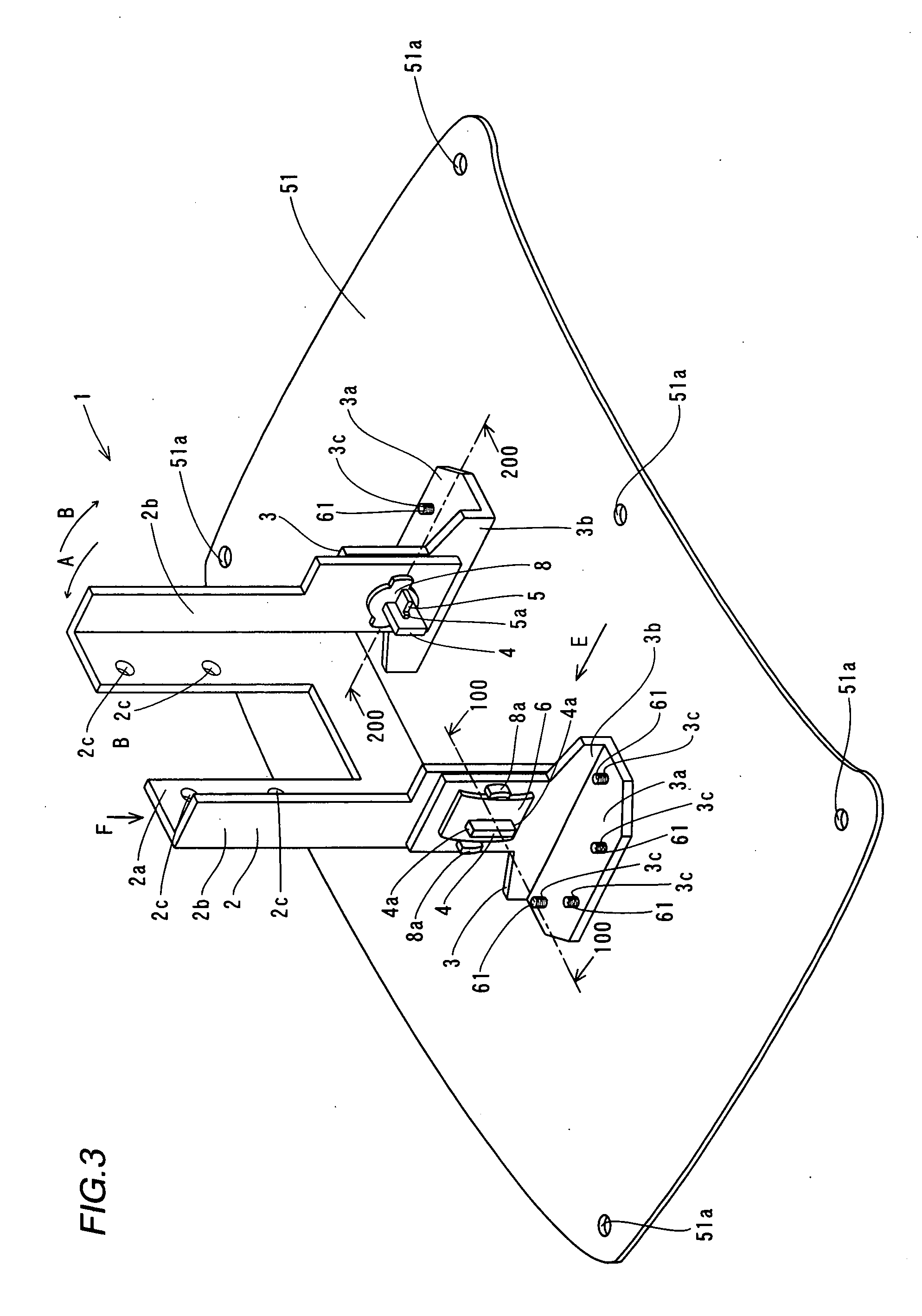
[0048] As shown in FIGS. 3 and 4, the display support mechanism 1 comprises a liquid crystal display portion support member 2, a pair of base...


PUM


Abstract

This display support mechanism comprises a support shaft provided in the form of a plate, a display screen support member, having a first hole receiving the platelike support shaft, provided on the side of a display screen and a base support member, having a second hole receiving the platelike support shaft, provided on the side of a base, and at least either the first hole or the second hole receiving the platelike support shaft is provided in the form of a sector while the display screen support member is rotatable about the platelike support shaft serving as an axis of rotation in the angular range of the sector.

Description

BACKGROUND OF THE INVENTION [0001] 1. Field of the Invention [0002] The present invention relates to a display support mechanism, and more particularly, it relates to a display support mechanism capable of supporting a display screen in a state inclined by a prescribed angle. [0003] 2. Description of the Background Art [0004] A display support mechanism capable of supporting a display screen in a state inclined by a prescribed angle is known in general, as disclosed in Japanese Patent Laying-Open No. 2000-200048 and Japanese Utility Model registration Nos. 3106183 and 3111702, for example. Each of the patent documents such as the aforementioned Japanese Patent Laying-Open No. 2000-200048 discloses a support structure for a display screen employing a round shaft as an axis of rotation for inclining the display screen by a prescribed angle with respect to a base. [0005] In the structure employing the round shaft as the axis of rotation for inclining the display screen by a prescribed ...

Claims


Application Information

Patent Timeline
IPC IPC(8): F16M11/00
CPCF16M11/10F16M2200/08Y10S248/917Y10T16/538Y10S248/919Y10T16/5385
Inventor SAWAI, KUNIOYOKOTA, KATSUYUKI
Owner FUNAI ELECTRIC CO LTD
Why Eureka
Try Eureka