Electronic device with integrated optical navigation module and microlens array therefore

Active Publication Date: 2007-09-20
PIXART IMAGING INC
View PDF15 Cites 46 Cited by
  • Summary
  • Abstract
  • Description
  • Claims
  • Application Information

AI Technical Summary

Benefits of technology

[0013] Aspects of the invention relate to optical navigation using a microlens array, and more particular

Problems solved by technology

However, while optical mice are used with computers, optical navigation modules are not used for these handheld devices.
Thus, handheld devices are not typically used with external devices to perform on-screen navigation, making the inclusion of conventional optical navigation technologies impractical with the handheld devices.
However, such mechanical devices have drawbacks in terms of overall aesthetic appeal, are liable to wear out from prolonged use, and are limited in terms of the navigation directions.
Therefore, in order to increase range of on screen movement, there need to be increased numbers of switches, which increases the complexity of the navigation module and exacerbates space constraints in a typical hand held device.
Thus, existing rocker switch technology is not suitable for providing cursor movement similar to that performed on computers using mice

Method used


Image

  • Electronic device with integrated optical navigation module and microlens array therefore
  • Electronic device with integrated optical navigation module and microlens array therefore
  • Electronic device with integrated optical navigation module and microlens array therefore

Examples


Embodiment Construction

[0045] Reference will now be made in detail to the present embodiments of the present invention, examples of which are illustrated in the accompanying drawings, wherein like reference numerals refer to the like elements throughout. The embodiments are described below in order to explain the present invention by referring to the figures.

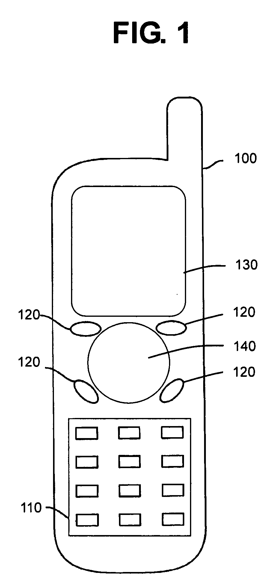
[0046]FIG. 1 shows a phone 100 utilizing an optical navigation device 140 according to an aspect of the invention. The phone 100 is shown as a cellular phone, but may be a wired or wireless phone in other aspects. The phone 100 includes a primary keypad 110, including alphanumeric and other like keys for use and entering numbers and / or characters. The phone 100 includes specific function keys 120 which provide specific functionalities such as send, end-call, and other like commands. Above the specific function keys 120 is a display 130. The display 130 displays information relevant to the user, and can include preset images and video received at the ...


PUM


Abstract

A portable device includes a transparent surface; a microlens array having lenslets, each lenslet forming a corresponding image of an object using light received through the transparent surface; a light sensor having pixels, each pixel corresponding uniquely to one of the plurality of lenslets, to detect the formed images of the object; and a controller to use the detected images to determine a motion of the object relative to the transparent surface, and to output the detected motion to a display for use in navigating a cursor and/or a menu on the display according to the determined motion. The portable device can be used in a telephone, personal digital assistant, and/or other handheld devices which control navigation on a display included in the device or external to the device.

Description

BACKGROUND OF THE INVENTION [0001] 1. Field of the Invention [0002] Aspects of the invention relate to optical navigation using a microlens array, and more particularly, to an electronic device having an integrated optical navigation module using a flat-type microlens array. [0003] 2. Description of the Related Art [0004] Conventionally, navigation modules (i.e., computer mice) come in a wide variety of shapes having different features, sizes and prices. Navigation modules are categorized according to how the motion is sensed. Specifically, optical navigation modules use optical motion sensing. In contrast, mechanical navigation modules use mechanical motion sensing. While the mechanical mice were the earlier of the two types of navigation modules, the optical navigation modules have begun to gain increased acceptance. [0005] Early versions of optical navigation modules were used in the context of personal computers and relied upon fine lines on a specific grid in order to perform t...

Claims


Application Information

Patent Timeline
IPC IPC(8): G06M7/00
CPCG06F3/0421
Inventor GRUHLKE, RUSSELL W.HELBING, RENE P.
Owner PIXART IMAGING INC
Why Eureka
Try Eureka