
Illumination system for a projection system

a projection system and projection system technology, applied in fixed installation, lighting and heating equipment, instruments, etc., can solve the problems of low collection efficiency of 0.7 inch dmd panels in dual lamp collection systems, limited commercially available uhp lamps with arc lengths of 1.5 mm or less, and low power consumption of high-power uhp lamps with short arc lengths

Inactive Publication Date: 2005-04-12
DELTA ELECTRONICS INC
View PDF8 Cites 54 Cited by
  • Summary
  • Abstract
  • Description
  • Claims
  • Application Information

AI Technical Summary

Problems solved by technology

Second, there are projectors using reflective digital micromirror device (DMD) chips.
Currently, commercially available UHP lamps with arc length of 1.5 mm or less are limited to approximately 250 to 300 watts of power.
However, high power (such as 600 watt) UHP lamps with short arc lengths are currently not commercially available.
However, both of these dual lamp collection systems still have low collection efficiencies for 0.7 inch DMD panels due to the two fold increase in beam cross section relative to a single lamp design.
Having a smaller collection aperture necessitated by the smaller DMD panel renders both dual lamp systems with undesirably low collection efficiencies.

Method used


Image

  • Illumination system for a projection system
  • Illumination system for a projection system
  • Illumination system for a projection system

Examples


Embodiment Construction

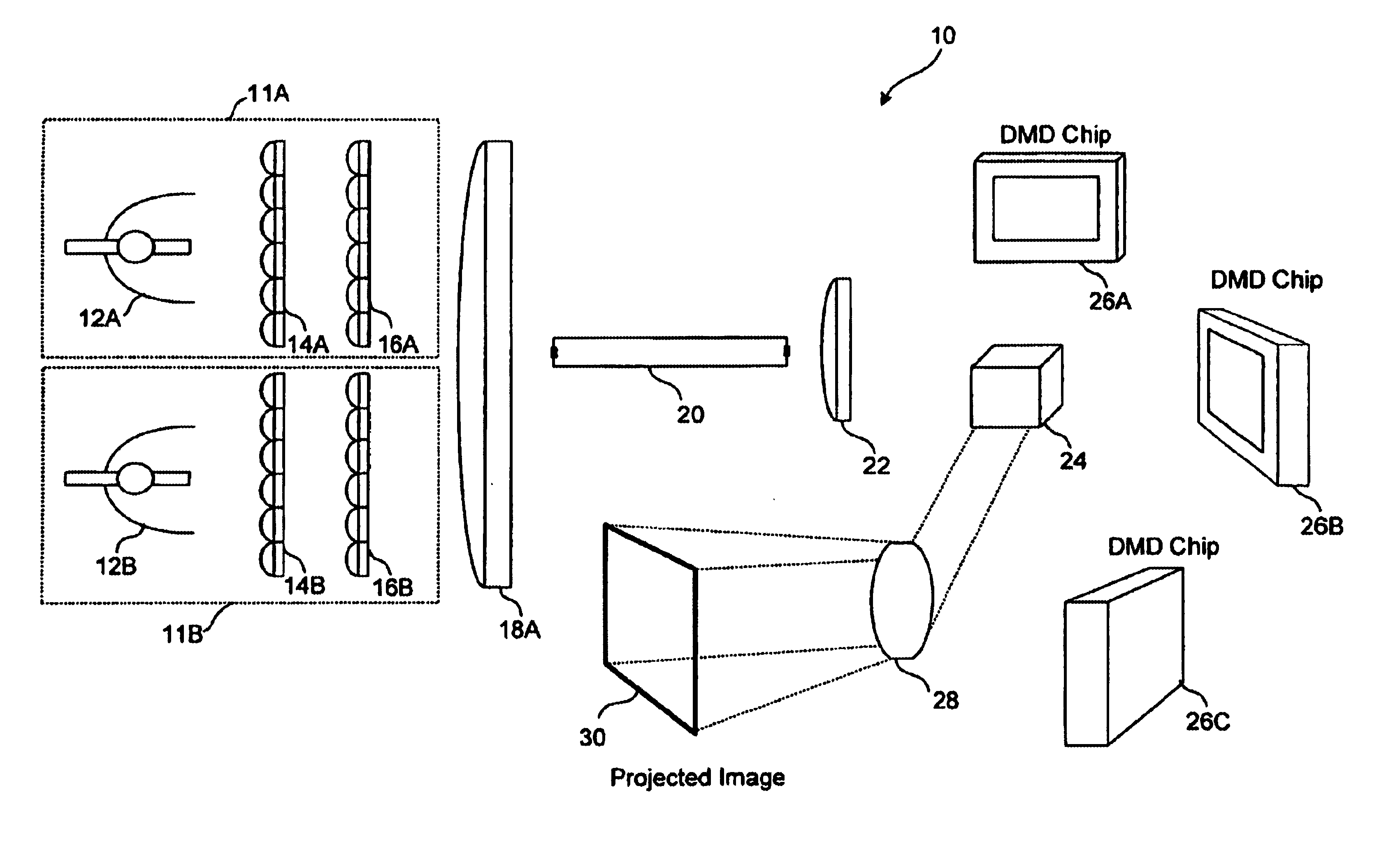
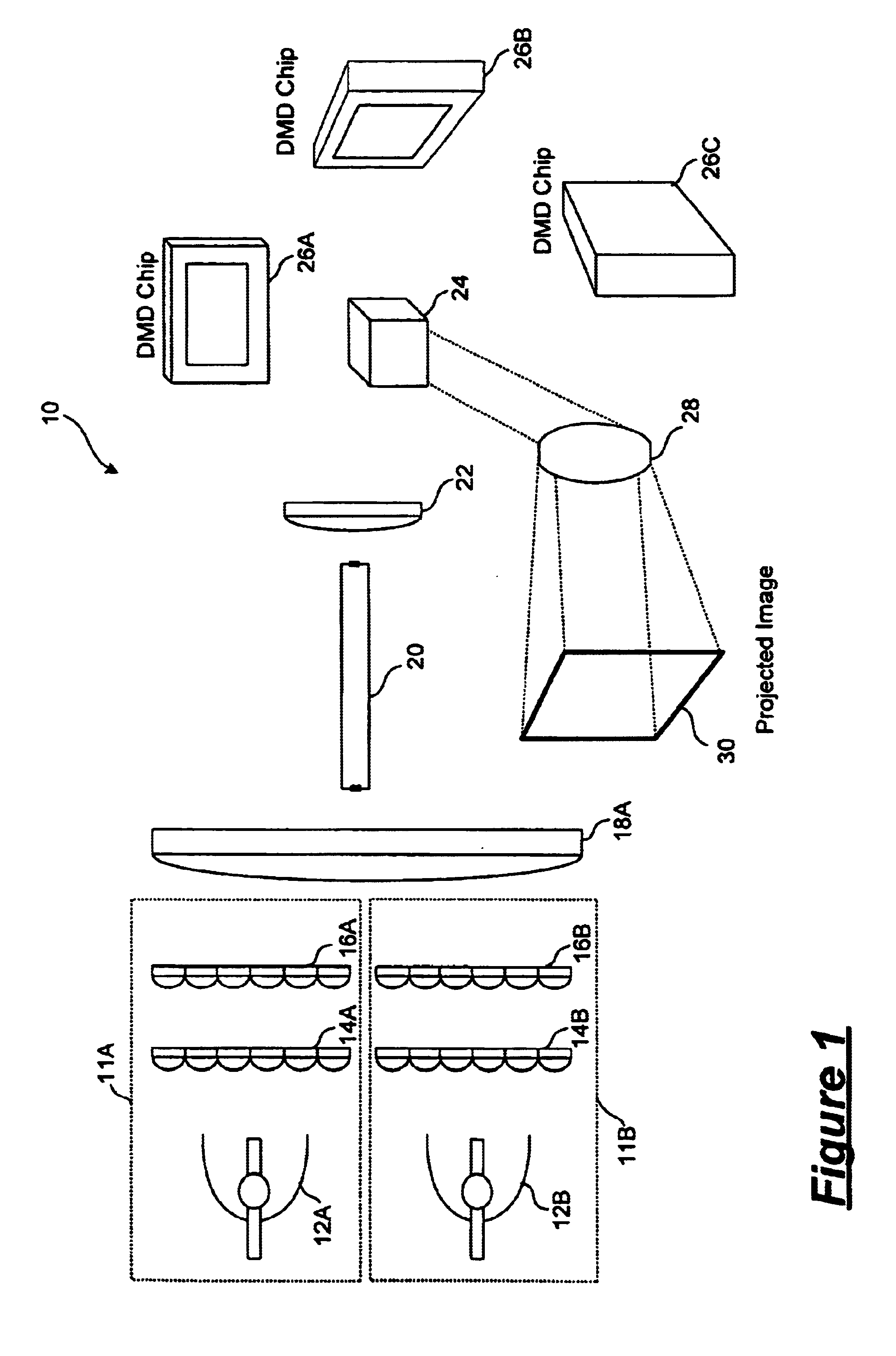
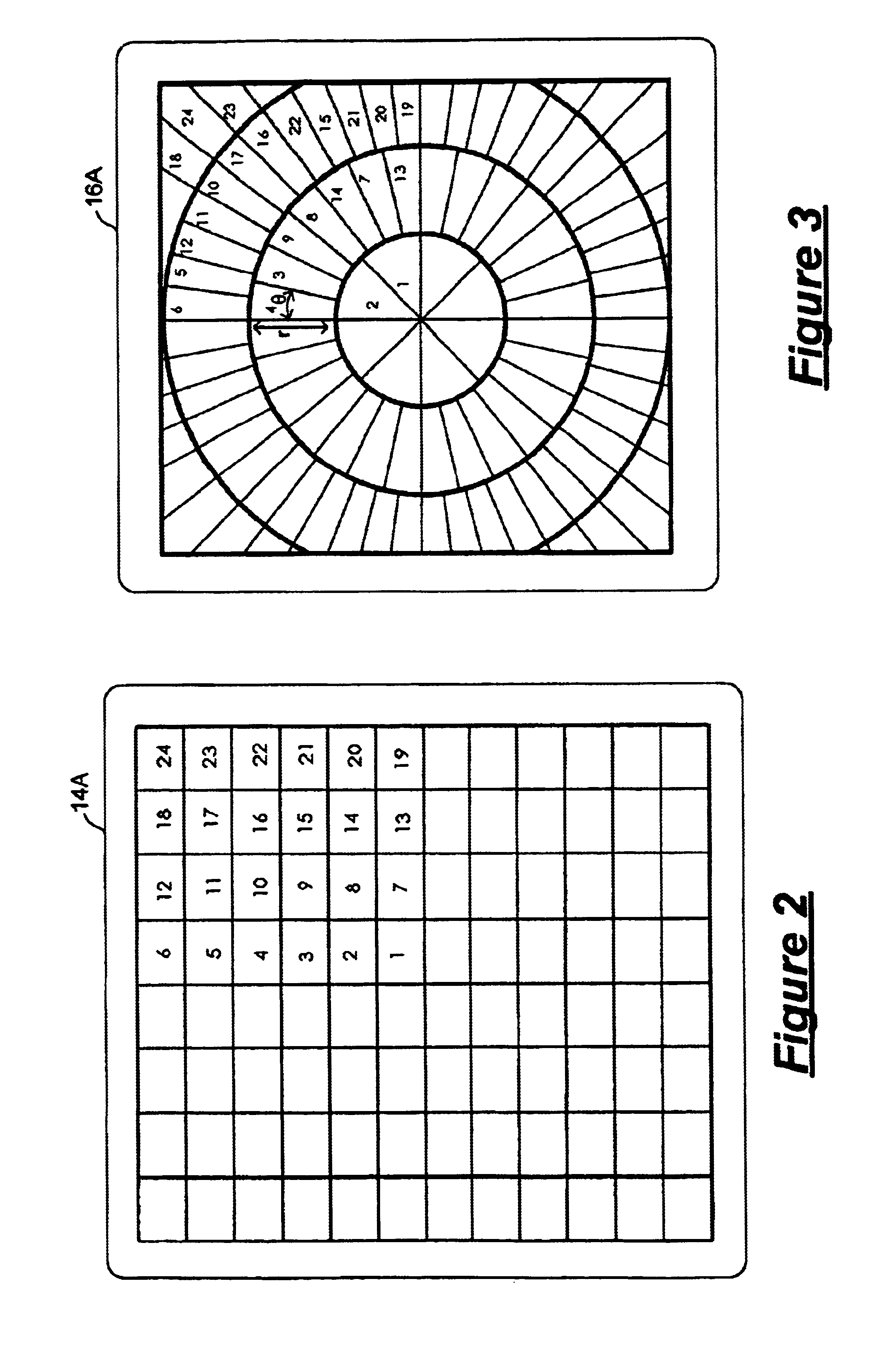
In accordance with the principles of the present invention, an illumination system for use in a digital projector includes a light source emitting a source of white light and a lens array system for collecting the emitted light. The light source includes a light emitting element, such as a lamp, and a parabolic reflector, concentrating and directing light onto the lens array system. The lens array system includes a first lens plate having an array of rectangularly shaped lenslets and a second lens plate having a radially arranged array of wedge shaped lenslets. There is a one to one correspondence between lenslet elements in the first lens plate and the lenslet elements of the second lenslet plate. Each of the radially oriented wedge shaped lenslets in the second lens plate has dimensions determined by the maximum beam divergence angle of the light source and the maximum divergence angle of the corresponding light emitting element in the first lens plate. The maximum beam divergence...


PUM


Abstract

An illumination system for illuminating an object includes a light source and a lens array system. The light source includes an illumination element emitting light rays and surrounded by a parabolic reflector. The lens array system includes a first lens array plate and a second lens array plate. The first lens array plate includes a matrix of lenslets where, in one embodiment, each lenslet has a shape matching the aspect ratio of the object to be illuminated. The second lens array plate includes a radial pattern of wedge shaped lenslets each corresponding to a lenslet in the first lens array plate. Each wedge shaped lenslet in the second lens array plate has dimensions that are selected to provide a radial and theta collection angles matching the maximum divergence angle of the light source and the maximum divergence angles of the corresponding lenslet in the first lens array plate.

Description

FIELD OF THE INVENTIONThe invention relates to an illumination system for illuminating an object and, in particular, to an illumination system with improved light collection for use in digital projectors.DESCRIPTION OF THE RELATED ARTData projectors, also known as digital projectors, are used for projecting images, usually color images, onto a screen. These projectors generally employ one of two types of data projection technologies. First, there are projectors using liquid crystal display (LCD) panels that act as the image forming device. Second, there are projectors using reflective digital micromirror device (DMD) chips. DMD chips are silicon based chips having movable microelectromechanical mirrors constructed thereon that act as the image forming device. The latter type of projectors is sometimes referred to as DMD projectors or digital light processing (DLP) projectors.Front projectors using a single 0.7-inch diagonal DMD panel are known. The single-chip projectors employ a fr...

Claims


Application Information

Patent Timeline
IPC IPC(8): F21V7/00G03B21/20H04N9/31
CPCH04N9/315G03B21/2026H04N9/3197
Inventor HAVEN, THOMAS J.VATNE, ROLF S.
Owner DELTA ELECTRONICS INC
Learn More