Lensed tapered optical waveguide

a tapered optical waveguide and tapered aperture technology, applied in waveguides, instruments, lighting and heating apparatuses, etc., can solve the problems of large numerical aperture combined with small area, unsuitable optical components, and inability to adapt to large numerical apertures

Inactive Publication Date: 2005-03-03
MEADOWSTAR ENTERPRISES
View PDF4 Cites 42 Cited by
  • Summary
  • Abstract
  • Description
  • Claims
  • Application Information

AI Technical Summary

Problems solved by technology

A large numerical aperture combined with a small area may be unsuitable for the optical components to which light from the system may be coupled.
While lenses provide an efficient means of transforming input areas and divergence angles of light, they require a certain amount of space in which to operate.
Also, they are not well adapted to large numerical apertures.
Tapered light pipes, however, must be relatively lengthy to transform light efficiently.
As may be seen in FIG. 2, the dual-ellipsoid system suffers from the same disadvantage as the dual-paraboloid system in that a large angle is produced between ray a and ray c at the target.
This dual-ellipsoid system suffers from the same disadvantage as the above-mentioned dual-paraboloid and dual-ellipsoid systems in that a large angle is produced between ray a and ray c at the target.
Such a large numerical aperture will result in a loss of coupling efficiency in subsequent optical elements.
But if the input area is reduced to reduce the numerical aperture at the output, less light will be coupled into the tapered light pipe in the first place, reducing the overall collection efficiency of the system.
A longer tapered light pipe, however, may require more space.
Matching an input aperture at the target to an arc, however, does not necessarily match it with the final output device, e.g. a fiber or projection engine.

Method used


Image

  • Lensed tapered optical waveguide
  • Lensed tapered optical waveguide
  • Lensed tapered optical waveguide

Examples


first embodiment

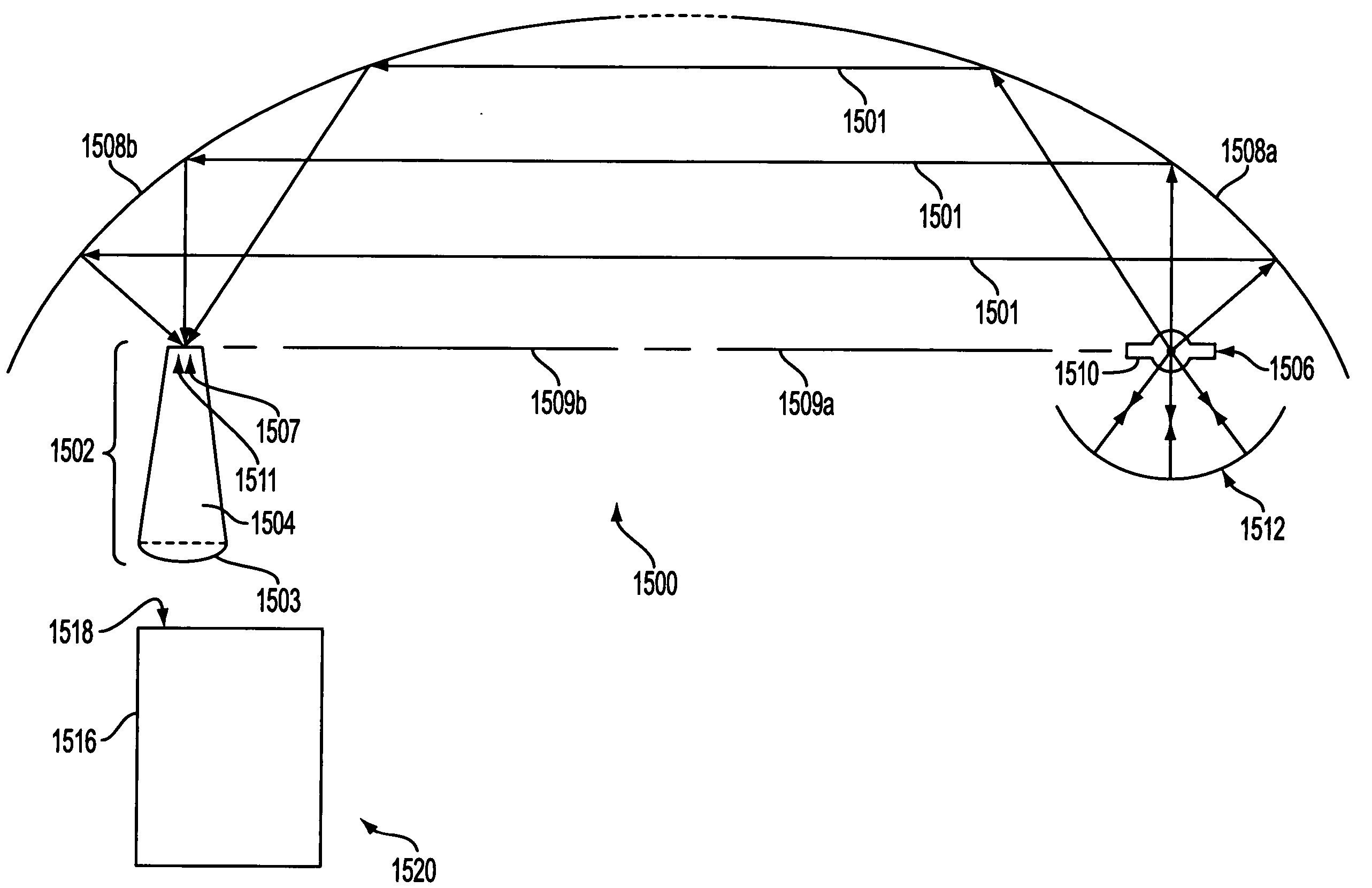
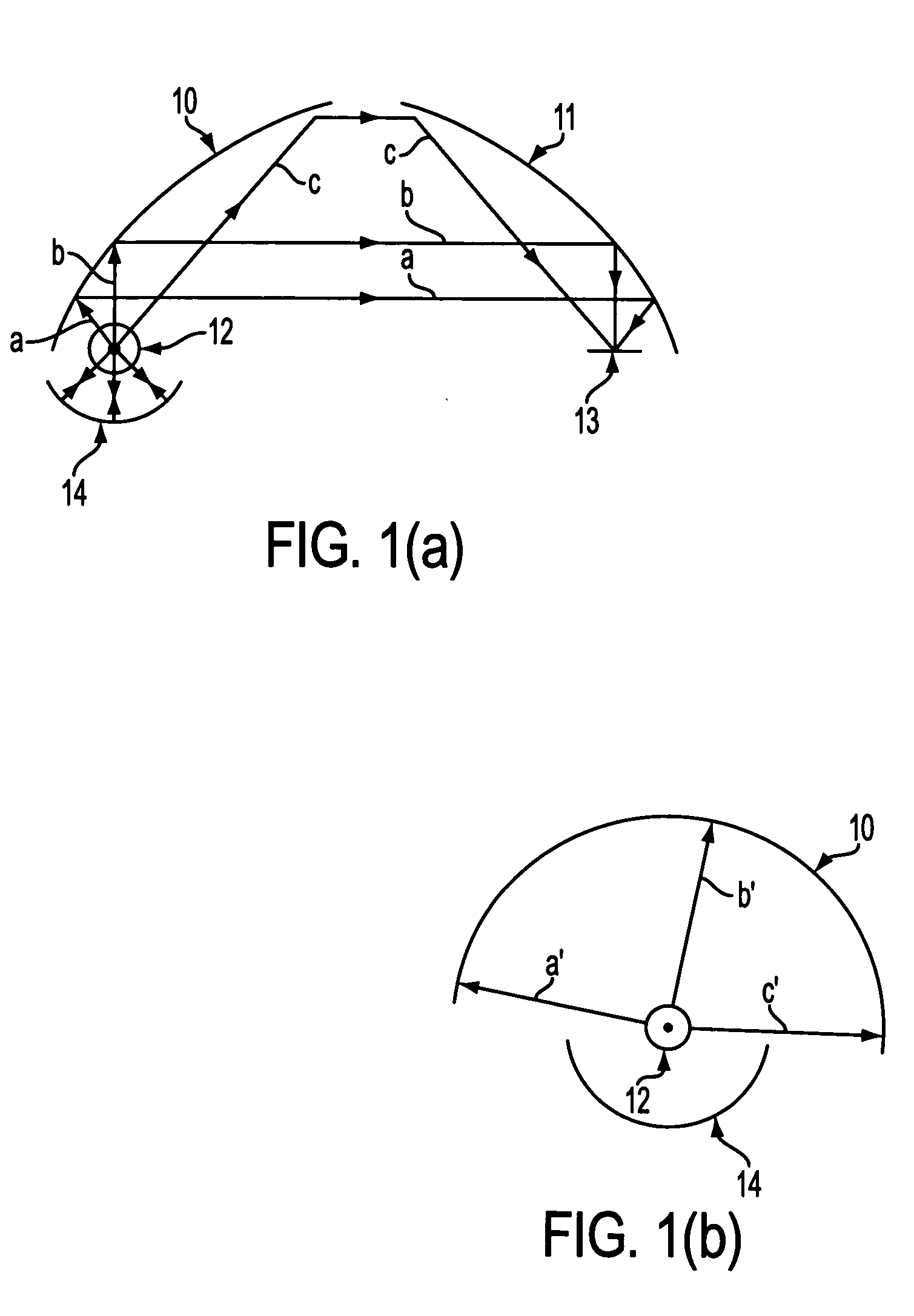
In a first embodiment, as shown in FIG. 10a, the collecting and condensing system 1000 has a reflector 1008 having a first focal point 1010 and a second focal point 1011 arranged around a source 1006 of electromagnetic radiation 1001 so that source 1006 may be located substantially proximate to first focal point 1010 of reflector 1008. Reflector 1008 may be, e.g. a substantially ellipsoidal, toroidal, spheroidal, or paraboloidal surface of revolution. Source 1006 produces rays of electromagnetic radiation 1001 that are reflected by reflector 1008 toward second focal point 1011, converging substantially at second focal point 1011.

second embodiment

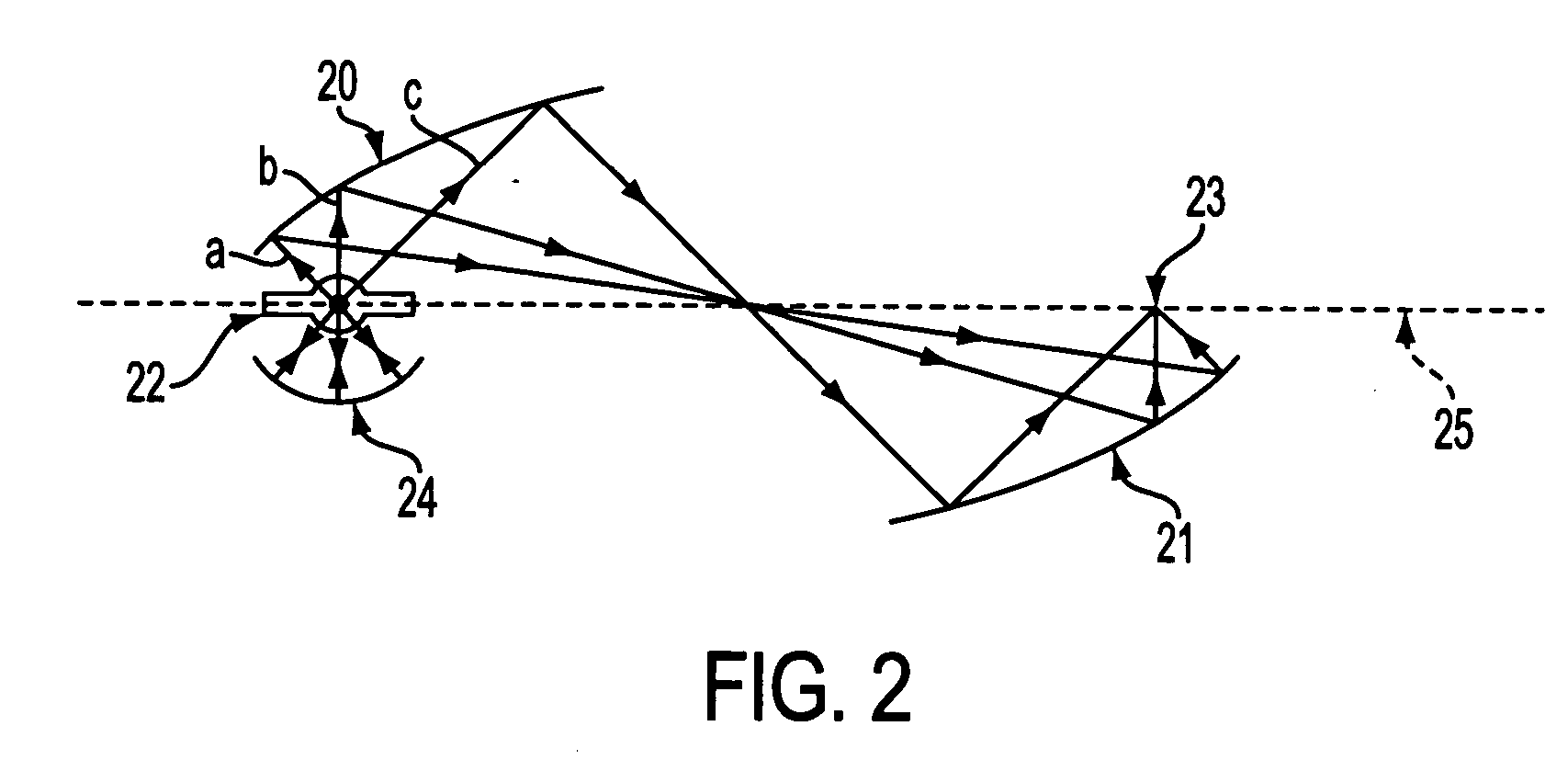
In a second embodiment, as shown in FIG. 10b, reflector 1008 comprises a primary reflector 1008a having a first optical axis 1009a and a first focal point 1010 substantially on the first optical axis 1009a, and a secondary reflector 1008b having a second optical axis 1009b and a second focal point 1011 substantially on the second optical axis 1009b which may be arranged substantially symmetrically to primary reflector 1008a. Primary reflector 1008a may be arranged around source 1006, so that source 1006 may be located substantially proximate to first focal point 1010 of primary reflector 1008a. First optical axis 1009a may be substantially collinear with second optical axis 1009b. Source 1006 produces rays of electromagnetic radiation 1001 that are reflected by primary reflector 1008a toward secondary reflector 1008b, converging substantially at second focal point 1011.

Both of reflectors 1008a and 1008b may be, e.g. substantially ellipsoidal or paraboloidal surfaces of revolution. ...

third embodiment

In a third embodiment, also shown in FIG. 10a, a retro-reflector 1012 may be placed to reflect at least part of that portion of electromagnetic radiation 1001 that does not impinge directly on reflector 1008 back toward reflector 1008 through first focal point 1010 to increase the flux intensity of the converging rays. In a preferred embodiment, additional reflector 1012 may be a spherical retro-reflector disposed on the side of source 1006 opposite reflector 1008 to reflect electromagnetic radiation 1001 emitted from source 1006 in a direction away from reflector 1008 back toward reflector 1008 through first focal point 1010 of reflector 1008.

In one embodiment, source 1006 may be a light-emitting arc lamp. Source 1006 may be, e.g., a xenon lamp, a metal halide lamp, an HID lamp, or a mercury lamp. In an alternative embodiment, source 1006 may be a filament lamp.


PUM


Abstract

An optical coupling element for use in large numerical aperture collecting and condensing systems. The optical coupling element includes a curved surface such as a lens at the output of a tapered light pipe (TLP). The TLP in combination with the curved surface alters the divergence angle and the area of the light exiting the curved surface. Electromagnetic radiation emitted by a source is collected and focused onto a target by positioning the source of electromagnetic radiation substantially at a first focal point of a primary reflector so that the primary reflector produces rays of radiation reflected from the primary reflector that converge at a second focal point of the secondary reflector. The optical coupling element is positioned so that its input end is substantially proximate with the second focal point of the secondary reflector. The converging rays of radiation reflected from the secondary reflector pass through input end and are transmitted towards the curved surface, where their divergence angle and area are adjusted.

Description

BACKGROUND OF THE INVENTION 1. Field of the Invention This invention relates to waveguides that collect and condense light from a light source, transforming the area and divergence angle of the light from their input to their output with minimum loss of brightness. 2. Description of the Related Art The objective of systems that collect, condense, and couple electromagnetic radiation into a target such as a standard waveguide, e.g. a single fiber or fiber bundle, or output electromagnetic radiation to the input of a projection engine, is to maximize the brightness of the electromagnetic radiation at the target. There are several common systems for collecting and condensing light from a lamp for such illumination and projection applications. One optical collection and condensing systems, U.S. patent application Ser. No. 09 / 604,921, the disclosure of which is incorporated by reference, provides a dual-paraboloid reflector system. This optical collection and condensing system, as i...

Claims


Application Information

Patent Timeline
Patent Type & Authority Applications(United States)
IPC IPC(8): F21V8/00G02B5/00G02B6/10G02B6/26G02B6/42G02B7/00G02B17/00G02B19/00G02B27/00G02B27/09G03B21/00G03B21/14H04N9/31
CPCG02B6/0006G02B6/10G02B6/4206G02B6/4214G02B6/4298Y10S385/901G02B27/0994H04N9/315H04N9/3197G02B19/0047G02B19/0028G02B26/008
Inventor LI, KENNETH K.
Owner MEADOWSTAR ENTERPRISES
Why Eureka
Try Eureka