LED optical lens and illumination device thereof

an optical lens and illumination device technology, applied in semiconductor devices, lighting and heating apparatus, instruments, etc., can solve the problems of low illumination of light, waste, and high efficiency of light bulbs, and achieve the effect of improving the effective luminance of the target area

Inactive Publication Date: 2010-06-17
CREATE ELECTRONICS OPTICAL
View PDF3 Cites 39 Cited by
  • Summary
  • Abstract
  • Description
  • Claims
  • Application Information

AI Technical Summary

Benefits of technology

[0006]Therefore it is a primary object of the present invention to provide a LED optical lens and an illumination device thereof in which a light-source side surface and an image side surface of a first LED lens (optical lens) or a second LED lens are designed by the surface definition of freeform surfaces. Thus the optical lens has different curvatures along different axes. Therefore, the effective luminance on the target area is improved and

Problems solved by technology

However, in conventional road lights such as high-pressure sodium lamps, the efficiency of the light bulb is quite high but the illumination of the light

Method used


Image

  • LED optical lens and illumination device thereof
  • LED optical lens and illumination device thereof
  • LED optical lens and illumination device thereof

Examples


Embodiment Construction

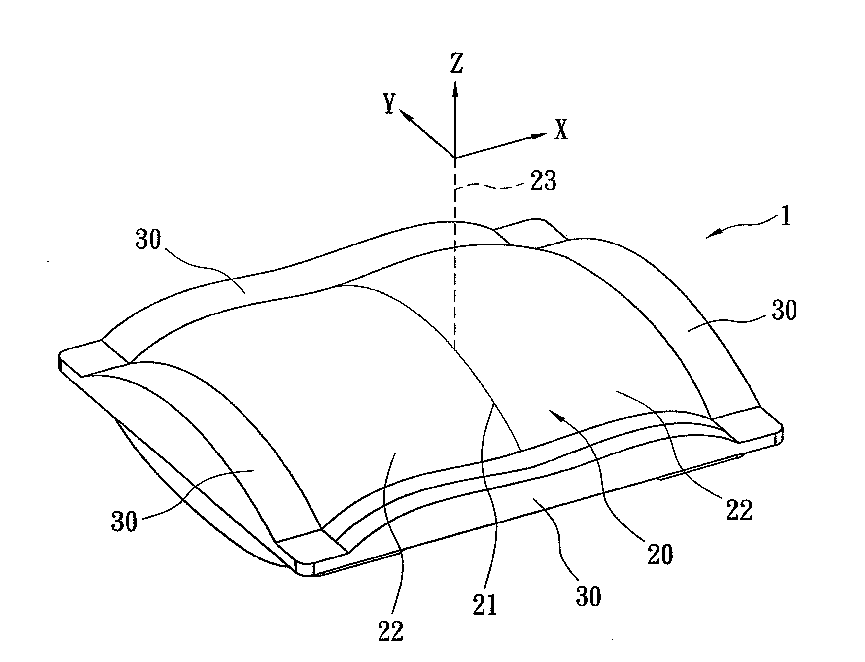
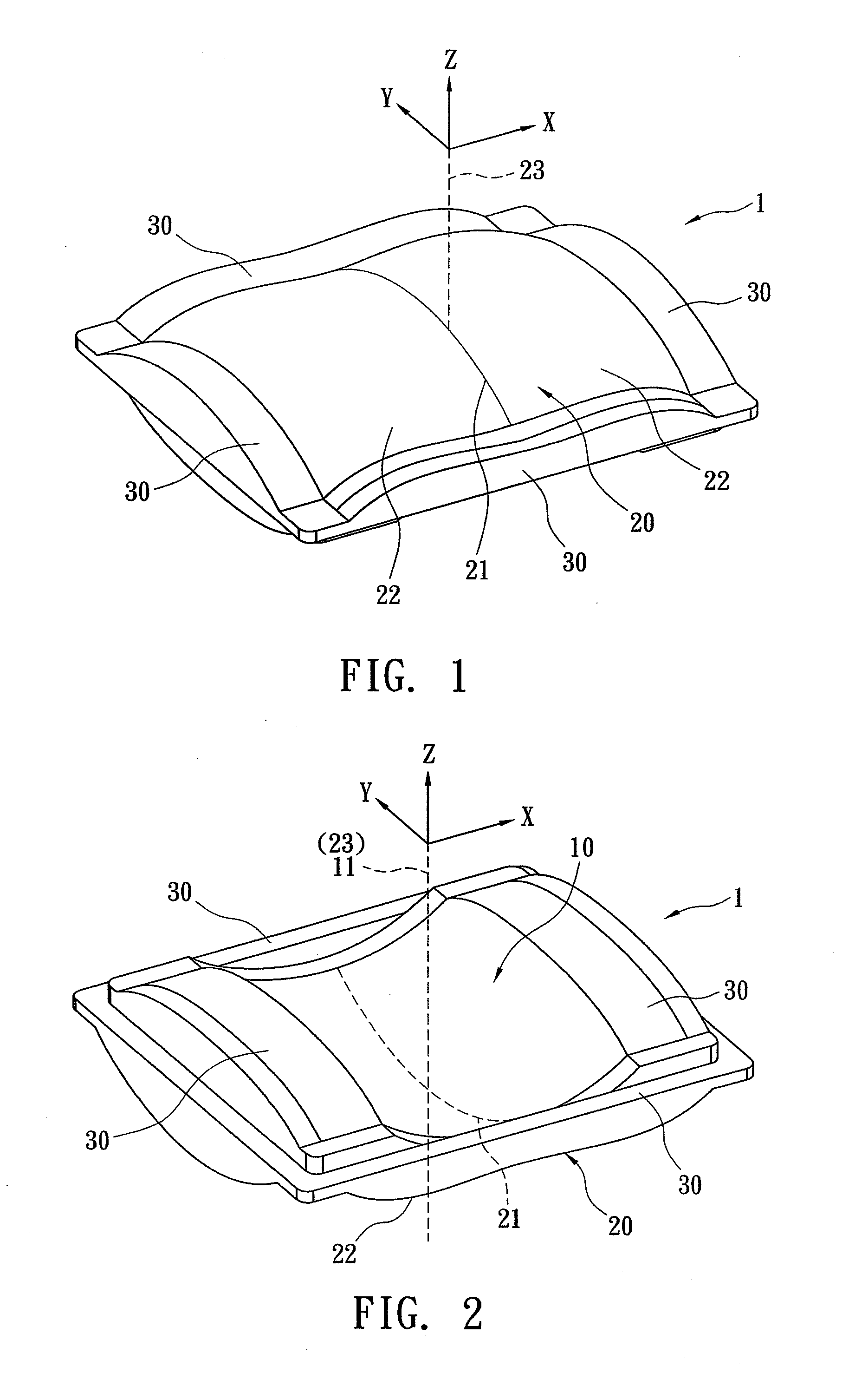
[0018]Refer from FIG. 1 to FIG. 6, an LED optical lens of the present invention can be a first lens or a second lens of LED. In this embodiment, the optical lens 1 is a second LED lens. As shown in figure, the optical lens 1 is used in combination with at least one LED 2. The optical lens 1 is a transparent lens having at least one light-source side surface 10 and one image side surface 20. Light from the LED 2 enters the optical lens 1, passes through the light-source side surface 10, the image side surface 20 and projects to the target area.

[0019]The present invention features on that: the light-source side surface 10 and the image side surface 20 are designed according to mathematical expressions of freeform surfaces. The mathematical expressions of freeform surfaces known in the optical field include a plurality of equations applied to the design of optical surfaces on lenses such as the following equation (1)—Anamorphic formula and the equation (2)—Toric formula. equation (1) A...


PUM


Abstract

A LED optical lens and an illumination device thereof are revealed. The optical lens includes a light-source side surface and an image side surface of the LED optical lens that both are designed respectively according to mathematical expressions of freeform surfaces such as Anamorphic formula and Toric formula Thus the optical lens has different curvatures along different axes. After light from LED emitting into the optical lens at a fixed incident angle, emergent light with different divergence angles along different axes is generated. For example, the divergence angle along the long axis is larger than that along the short axis. Therefore a uniform and near rectangular distribution pattern is formed on the target area Moreover, a plurality of optical lenses aligned along the same axes is arranged at a holder to form a lens array. The lens array is used together with a LED array so as to form a LED illumination device.

Description

BACKGROUND OF THE INVENTION[0001]The present invention relates to a LED optical lens and an illumination device thereof, especially to a first LED lens or a second LED lens whose optical surfaces on a light source side and on an image side are designed according to surface definitions of freeform (mathematical expressions of freeform surfaces) so that the optical lens having different curvatures along different axes. Light emitted from LED light sources passes through the optical lens to generate a near rectangular light distribution pattern with even illumination on a target area.[0002]LED has been applied to various fields widely, acting as light sources such as flashlights, desk lamps, vehicle lamps (headlights and / or taillights), road lights or lighting accessory of electronics such as camera flashlights, scanning light source etc. A plurality of LED is arranged into an array that works as a light source. The arrangement of LED is not restricted. It can be various patterns such ...

Claims


Application Information

Patent Timeline
IPC IPC(8): F21V5/00
CPCF21V5/04F21W2131/103G02B19/0061G02B27/0955G02B19/0014F21Y2101/02F21Y2115/10
Inventor LO, CHIH-WEICHU, I-LIN
Owner CREATE ELECTRONICS OPTICAL
Why Eureka
Try Eureka