
Polarization conversion light integrator

a polarization conversion and integrator technology, applied in the field of display systems, can solve the problems of increasing the component count and cost of the polarization recovery system, reducing the brightness of the screen from the center, and reducing the acceptance angle of the screen

Inactive Publication Date: 2005-08-11
JDS UNIPHASE CORP
View PDF11 Cites 49 Cited by
  • Summary
  • Abstract
  • Description
  • Claims
  • Application Information

AI Technical Summary

Benefits of technology

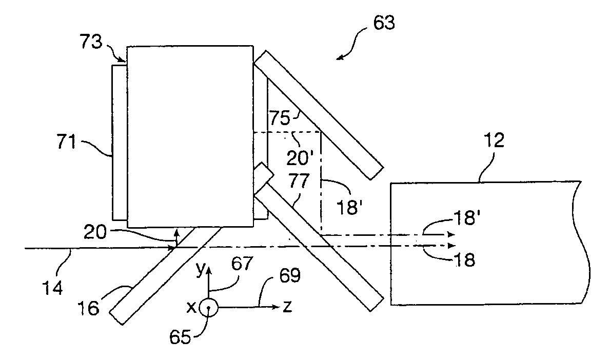
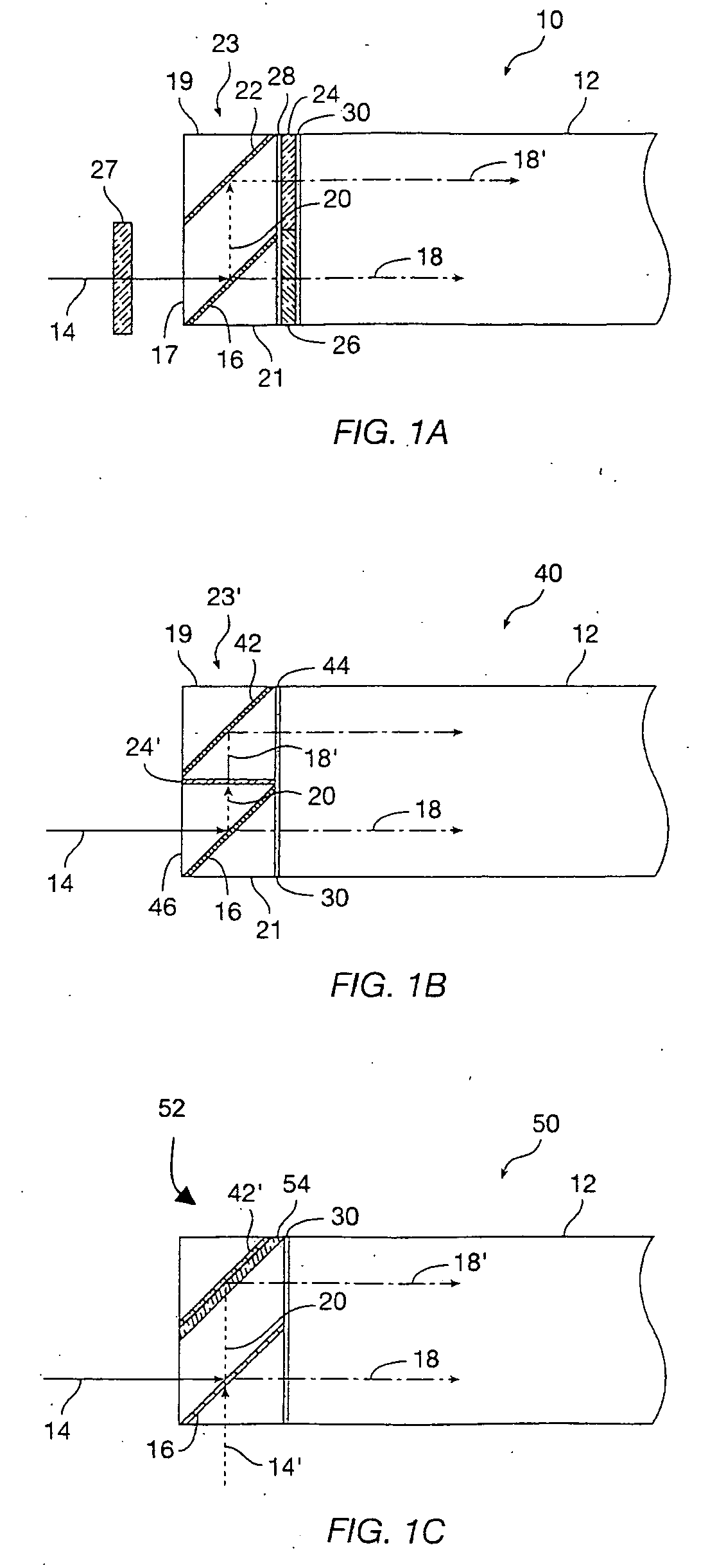
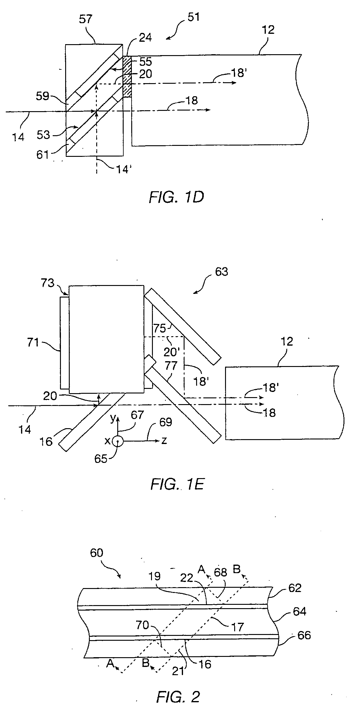
[0013] The present invention provides compact, efficient polarization conversion of light for use in projection display systems and similar applications. In some embodiments, an input light waveguide is assembled to a polarizing beam splitter with a high-temperature optical bond, such as an optical contact bond or with a clear high-temperature optical adhesive. In other embodiments, the input light waveguide is omitted, and light from a lamp or other light source is provided to a polarizing conversion assembly optically coupled to a light integrator. A first polarizing beam splitter has a high angle of acceptance, avoiding the need for a small numerical input aperture and associated input light waveguide. The polarizing beam splitter splits the light into a selected polarization portion and a non-selected polarization portion. A retarder plate is disposed in the optical path of the light having the non-selected polarization state. The retarder plate is a quarter-wave plate in some embodiments, and a half-wave plate in other embodiments, depending on the configuration of the polarizing beam splitter.

Problems solved by technology

However, even with homogeneous light from a light pipe the brightness of the screen typically decreases from the center to the edge of the screen.
However, light pipes are relatively bulky and add to the component count and cost of the polarization recovery system.
Some epoxy adhesives work acceptably well at relatively low temperatures, but do not provide sufficient reliability at the high temperatures and light flux encountered in some display systems.
Other epoxy adhesives work to higher temperatures, but are colored or tinted when cured, which affects the color balance of the light.

Method used


Image

  • Polarization conversion light integrator
  • Polarization conversion light integrator
  • Polarization conversion light integrator

Examples


Embodiment Construction

I. Introduction

[0028] Embodiments of the present invention provide polarization conversion systems for use in display systems and other applications. In some embodiments, light is directly coupled from a lamp system (arc and reflector) into the PCS without an input light pipe. A polarizing beam splitter with a wide acceptance angle provides efficient conversion and uniform contrast. The polarized light is provided to an output light integrator. In other embodiments, an input light pipe is used to illuminate the polarizing beam splitter with light having a small numerical aperture. High-temperature bonds in the optical path allow the PCS to work in systems having high flux and / or high operating temperatures.

[0029] Generally speaking, polarization recycling systems are particularly desirable for use with lamps having a small arc gap (≦1 mm) and larger panels (greater than about 20 mm), whereas PCSs might be preferable for use with lamps having larger arc gaps and with smaller panels....


PUM


Abstract

A polarizing conversion system uses a polarizing beam splitter and reflector with a polarization conversion element to convert light from a lamp to a selected polarization state before providing the light to a light integrator, such as a light pipe or light tunnel. The light integrator provides homogenized polarized light to a light modulator. The polarization conversion system avoids increases efficiency compared to absorptive or simple reflective polarizers with fewer components than polarization conversion systems using patterned retarder plates and lenslet arrays. In one embodiment, the conversion elements are held to avoid adhesive or other bonds in the optical path. In other embodiments, high-temperature optical adhesive or optical contact bonding is used to assemble optical components for high-temperature operation. In a particular embodiment, a single-crystal quartz retarder plate is thermally matched to glass components in the polarization conversion system.

Description

CROSS-REFERENCE TO RELATED APPLICATIONS [0001] Not applicable. STATEMENT REGARDING FEDERALLY SPONSORED RESEARCH OR DEVELOPMENT [0002] Not applicable. REFERENCE TO MICROFICHE APPENDIX [0003] Not applicable. BACKGROUND [0004] This invention relates generally to display systems, such as liquid crystal displays (“LCD's”) and projection displays, that use polarized light in applications such as color televisions, business projectors, and computer displays, and more particularly to a polarizing light integrator. [0005] Most LCD projectors and projection systems use linearly polarized light at a light valve. The light valve is generally an array of reflective or transmissive pixels that turn on and off in a synchronized fashion to form an image from light that is illuminating the light valve. The image from the light valve is then typically focused onto a display screen. [0006] It is desirable that the light illuminating a display screen have reasonably uniform intensity across the screen ...

Claims


Application Information

Patent Timeline
IPC IPC(8): G02B27/28G02F1/13357H04N9/31
CPCG02B27/283G02F1/13362H04N9/3197H04N9/315H04N9/3117
Inventor GREENBERG, MICHAEL R.MCGETTIGAN, ANTHONY D.DUELLI, MARKUSHRUSKA, CURTIS R.CATCHING, BENJAMIN F.
Owner JDS UNIPHASE CORP
Learn More