Supercharge Your Innovation With Domain-Expert AI Agents!

Mounting Strucuture for Fuel Pump of Vehicle Engine and Vehicle Installing the Same

a technology for mounting strucutures and fuel pumps, which is applied in the direction of machines/engines, transportation items, cycle equipments, etc., can solve the problems of increasing the number of such bolts, increasing the fixing time, and the need for high sealing of the mounting plate, so as to improve the sealing function

Inactive Publication Date: 2007-09-20
YAMAHA MOTOR CO LTD
View PDF7 Cites 12 Cited by
  • Summary
  • Abstract
  • Description
  • Claims
  • Application Information

AI Technical Summary

Benefits of technology

The present invention provides a fuel pump mounting structure for a vehicle engine that reduces the moment against the mounting plate of the fuel pump, by arranging the axis of the cylindrical pump body parallel to the mounting plate and overlapping the filter with the fuel pump. This structure can securely support the fuel pump under a stable condition without requiring a large and firm construction, and improve seal function of the fuel tank. The invention also provides a vehicle installing the fuel pump mounting structure.

Problems solved by technology

The fixing means cause increase of such bolts in number and increase of fixing time.
In addition, the mounting plate requires to be highly sealed because a fuel leaking problem is likely to happen.
This structure can cause problems regarding strength and seal function of the mounting plate, similarly to the structure disclosed in Patent Application Publication No. 2002-106440.
Also, the structure that the fuel pump is large spaced apart in the vertical direction is not suitable for a bottom surface of the fuel tank.

Method used


Image

  • Mounting Strucuture for Fuel Pump of Vehicle Engine and Vehicle Installing the Same
  • Mounting Strucuture for Fuel Pump of Vehicle Engine and Vehicle Installing the Same
  • Mounting Strucuture for Fuel Pump of Vehicle Engine and Vehicle Installing the Same

Examples


Embodiment Construction

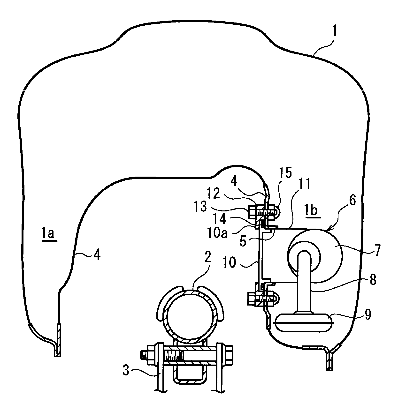
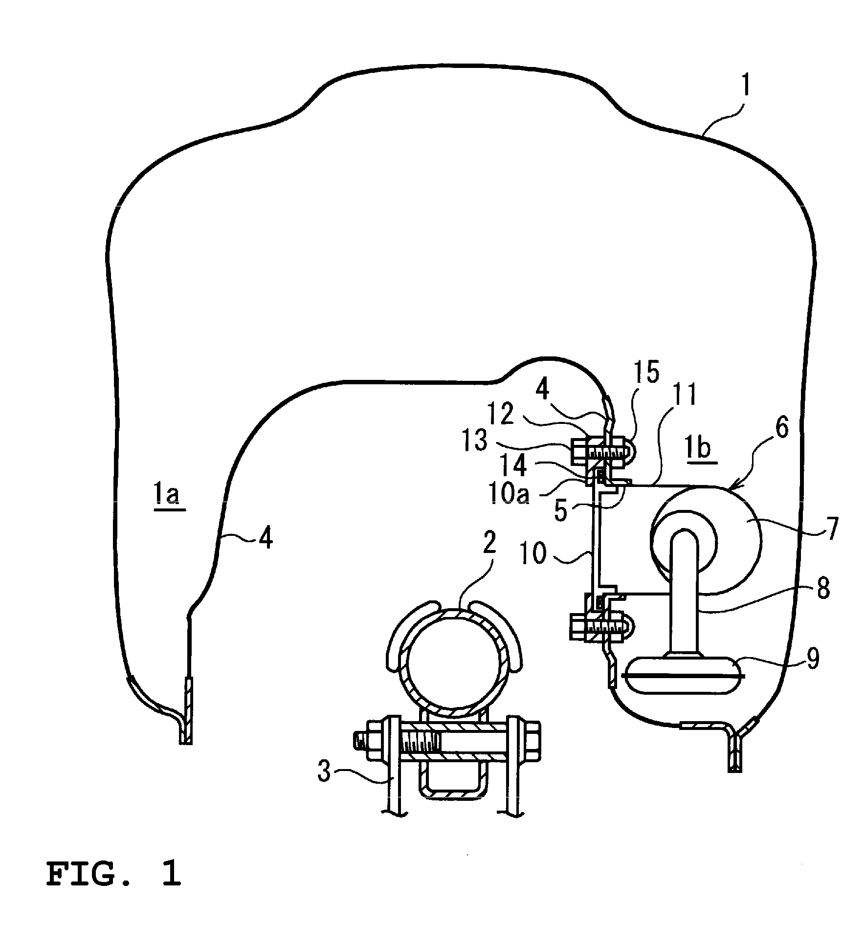
[0030]FIG. 1 is a vertical cross-sectional elevation view of an embodiment of the present invention. In the illustrated embodiment, a fuel pump structure is shown as being accommodated within a saddle type fuel tank that straddles a body frame of a motorcycle. The saddle type fuel tank 1 has a configuration to straddle a main frame 2 extending fore to aft along a vehicle body (not shown). The main frame 2 is affixed to a head pipe through which a steering shaft coupled with a handle bar that is not shown extends. The main frame 2 is a pipe-shaped frame and is disposed to extend to a location below a seat. The main frame 2 supports an engine (not shown) via an engine bracket 3.

[0031] The fuel tank 1 has right and left fuel reservoir sections 1a, 1b on the sides of the main frame 2. The fuel tank 1 also has an opening 5 defined at a side wall 4 located inside of the fuel reservoir section 1b on the right hand side of the figure. An inside space next to the opening 5 accommodates a fu...


PUM


Abstract

A fuel pump mounting structure has an opening in a side surface or a bottom surface of a fuel tank. A fuel pump assembly including a cylindrical pump body and a filter connected to a suction side of the pump body is accommodated in a space located inside of the opening. A flange section of a housing that encloses the pump body engages an outside surrounding area of the opening. A mounting plate covers the outside of the flange section. The fuel pump assembly is fixed to the opening through the flange section and the mounting plate. The axis of the pump body extends generally parallel to a mounting surface of the mounting plate, and the pump body and the filter overlap each other relative to a position in a direction of the axis. The mounting structure reduces the moment against the mounting plate, reliably supports the fuel pump under a stable condition without requiring a large and rigid construction, and improves the seal with the fuel tank.

Description

FIELD OF THE INVENTION [0001] The present invention relates to a mounting structure for a fuel pump accommodated in a fuel tank of a vehicle engine and a vehicle installing the fuel pump mounting structure. BACKGROUND ART [0002] A fuel supply device disposed within a saddle type fuel tank that straddles a body frame is disclosed in Patent Application Publication No. 2002-106440. A fuel pump mounting structure described in Patent Application Publication No. 2002-106440 has an opening formed in a surface located inside of the saddle type fuel tank. A base plate closes the opening. The fuel pump is disposed in an inner space of the tank and mounted such that an axis of the fuel pump extends generally parallel to the base plate. That is, the fuel pump extends along the side surface where the base plate is attached. A filter is coupled with a suction side located at an end portion of the fuel pump, wherein the end portion extends along the axis of the fuel pump. [0003] However, in the fu...

Claims


Application Information

Patent Timeline
Patent Type & Authority Applications(United States)
IPC IPC(8): B62J35/00B62J37/00F02M37/00F02M37/10
CPCB62J35/00F02M37/103F02M37/0094B62J37/00
Inventor ASAMURA, KINJISUZUKI, SATOSHIHIRANO, FUMITOHIRANO, EMIKO
Owner YAMAHA MOTOR CO LTD
Features
  • R&D
  • Intellectual Property
  • Life Sciences
  • Materials
  • Tech Scout
  • Unparalleled Data Quality
  • Higher Quality Content
  • 60% Fewer Hallucinations
Learn More