Method for controlling a wind power plant and corresponding wind power plant

a technology of wind power plant and control method, which is applied in the direction of electric generator control, variable speed operation control, rotor control, etc., can solve the problems of excessive problem of converting the regulation of wind power plant in the upper partial load range as a function of measured wind speed, subjecting the wind power plant to high loads, and achieving improved grid compatibility and reliability.

Inactive Publication Date: 2007-09-20
SENVION GMBH
View PDF30 Cites 77 Cited by
  • Summary
  • Abstract
  • Description
  • Claims
  • Application Information

AI Technical Summary

Benefits of technology

[0027] The object of the present invention is to create an improved and more reliable method of regulating a wind turbine in the range starting at a defined limit value and to offer improved grid compatibility.

Problems solved by technology

Ordinary operation of a wind turbine at which the nominal power output is regulated by adjusting the rotor blade is impossible at wind speeds higher than said shutdown speed because further exposure to mechanical loading would damage, even destroy the wind turbine.
However, abruptly shutting down wind turbines at wind shutoff speeds and especially so where the area contains many such wind turbines, may entail voltage or frequency dips in the public electricity grid.
However the practice of converting the wind turbine regulation in the upper partial-load range as a function of measured wind speed is exceedingly problematical.
Operating a wind turbine in an upper partial-load range involves subjecting the wind turbine to high loads caused by high wind speeds.
Turbulence implies that the speed at which the wind impinges the rotor surface is not uniform on said surface, instead the incident wind power is distributed unevenly.
At the same time one or more other rotor zones may be little wind-loaded or not at all, whereby at high turbulence the wind turbine may be subjected to very high changing loads and be damaged by them at once or in the long term.
Heretofore, however, no practical procedure has been available to reliably determine such basic wind speed conditions.
This procedure however incurs a well known lack of accuracy, the wind turbine rotor interferes much with the measurement.
Accordingly, clean-cut measurement is impossible.
Moreover this procedure allows only measuring wind conditions in one spot of the wind zone.
This known procedure is unable to transduce the turbulent wind speeds across the entire rotor.
To-date, for lack of sufficient testing, said systems have been put to practice only in isolated cases.
Moreover, these LIDAR and SODAR systems are very expensive and it appears that economically not every wind turbine can afford to have one, hence these systems appear impractical when actual wind conditions must be ascertained.
However wind turbine or rotor-speed regulation by means of load peaks is not advantageous because grid compatibility and large mechanical rotor inertia of the wind turbine entail respectively slow changes in power output and in rotor speed enduring well after said peaks have decayed.
However, the patent document cited just above does not disclose using such detected load values, and accordingly regulation in the upper partial-load range discussed in the European patent document EP 1 230 479 can only be carried out as a function of wind speed.
However, absent high costs, heretofore it has been impossible to detect a wind speed that would represent the actual wind conditions and therefore said above discussed previous procedures incur the substantive drawback that they make practical implementation difficult.
The regulation algorithms of the known state of the art moreover are highly susceptible to interference especially for high wind speeds where fluctuations in such wind speeds are related to large fluctuations of incident wind power.

Method used


Image

  • Method for controlling a wind power plant and corresponding wind power plant
  • Method for controlling a wind power plant and corresponding wind power plant
  • Method for controlling a wind power plant and corresponding wind power plant

Examples


Embodiment Construction

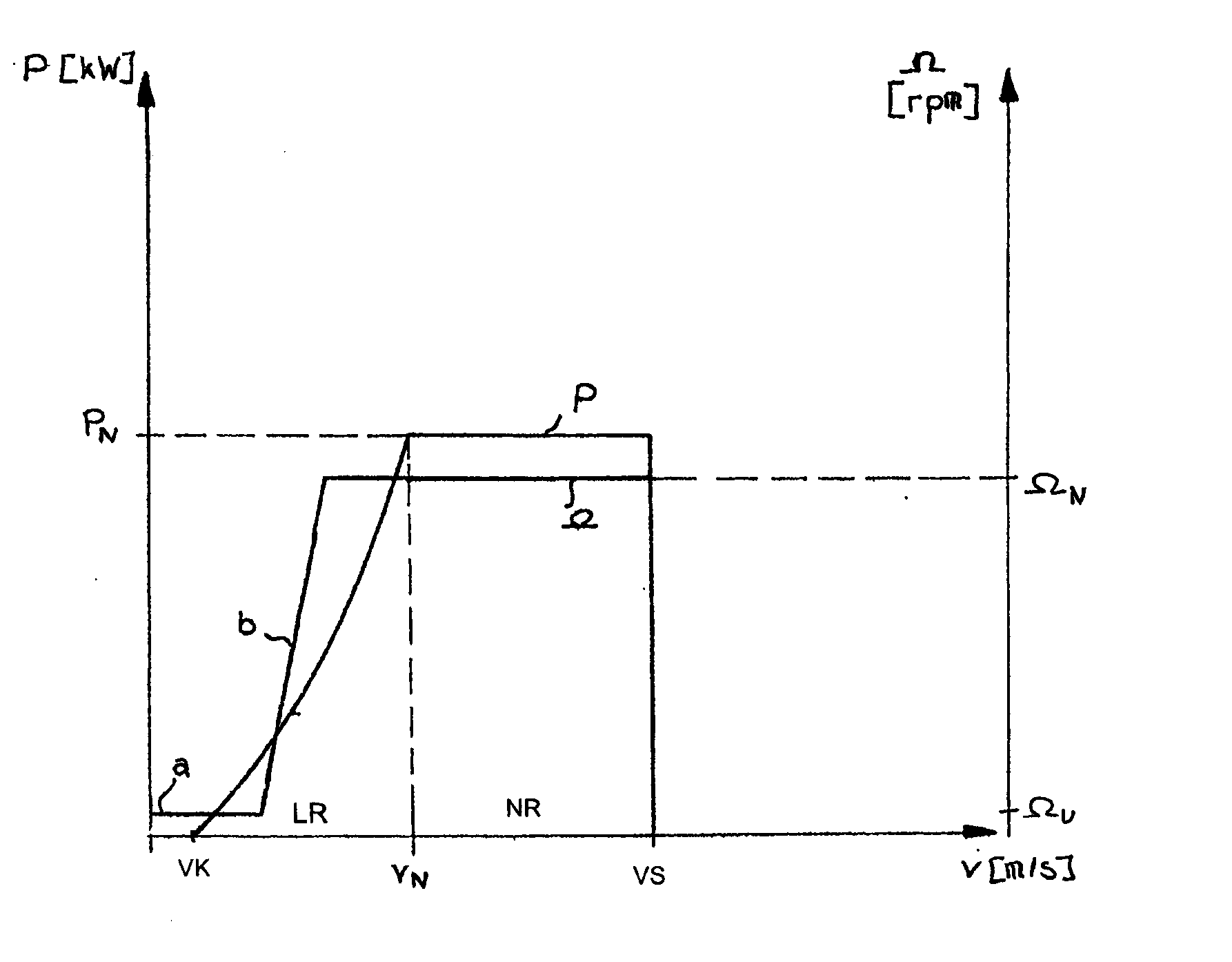
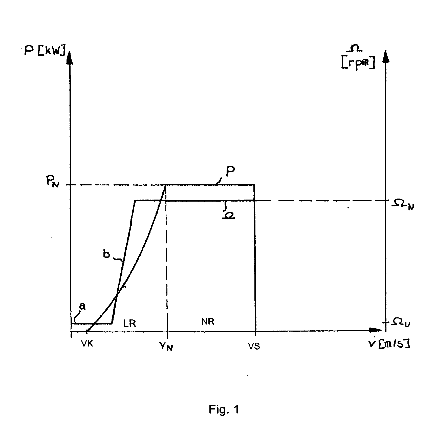
[0084]FIG. 1 already was discussed above in relation to the state of the art and need not be elucidated again here.

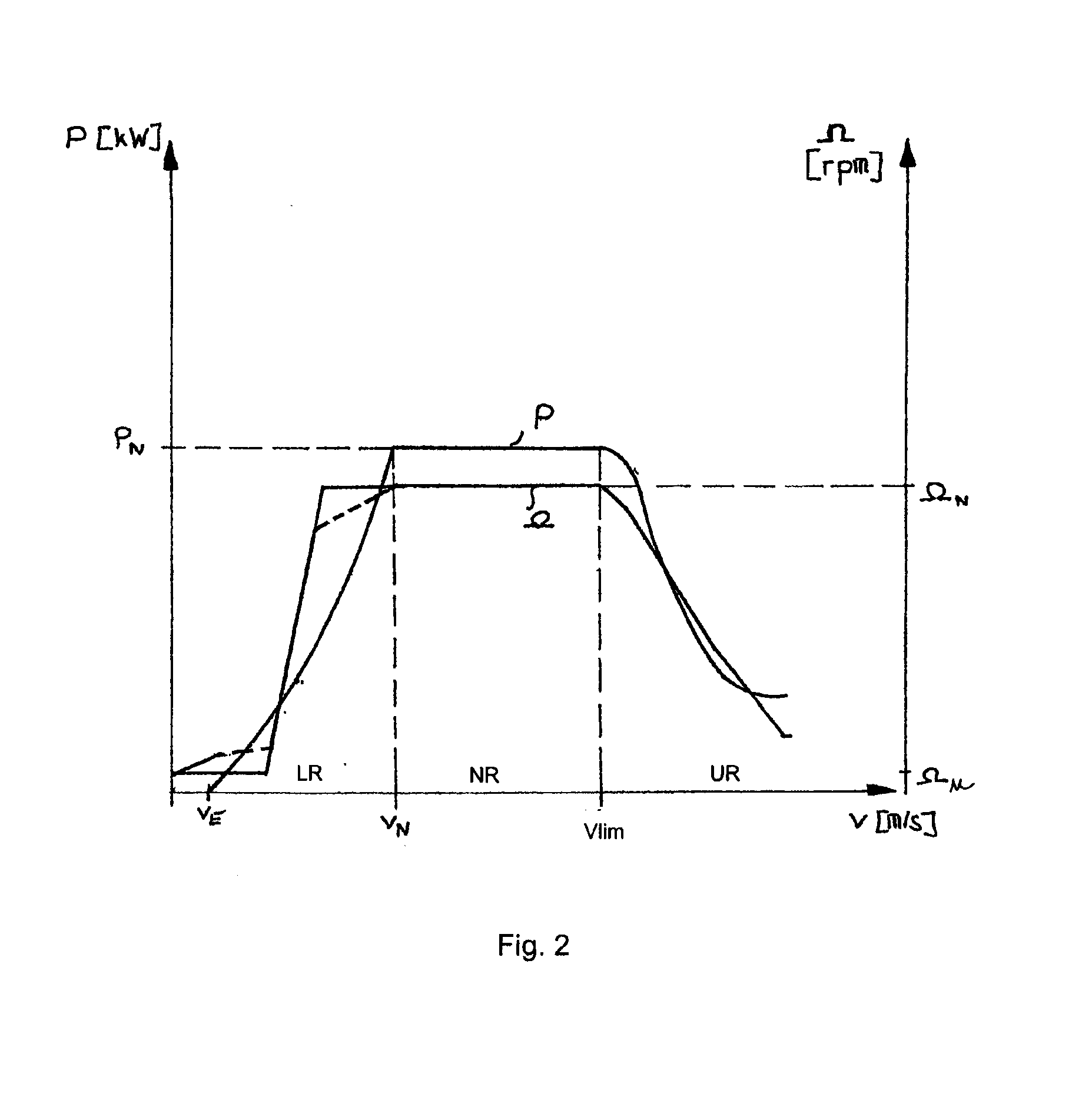
[0085]FIG. 2 also was discussed above in relation to the state of the art and needs only a few more comments below.

[0086] In its lower partial-load range LR, FIG. 2 shows in solid lines a rotor-speed characteristic curve such as would attain optimal power output in a limited and predetermined rotor-speed range between Ωu and ΩN. Conventionally, regulation is implemented by a PI or a PID control acting on the generator torque as a function of rotor speed to attain the rotor-speed ramp for operation at an optimal high operating rate. Alternatively and as already mentioned above, to attain an especially simple control algorithm, a simple relation between rotor speed and torque, for instance a tabular function, may be defined. Illustratively such a fixed rotor-speed / torque characteristic curve would lead to the dashed rotor-speed characteristic curve. The horizontal plate...


PUM


Abstract

Reduction in power output or rotor speed of a wind turbine above a defined limit value, the reduction not being implemented based on the measured wind speed, but on an input value which on one hand is easily detected physically and by control technology and on the other hand is a good indicator of mechanical stresses on the wind turbine. The invention uses the rotor-blade angle as the input value in a manner that starting at the limit value, the reduction in power output or in rotor speed is adjusted as a function of the rotor-blade angle.

Description

BACKGROUND OF THE INVENTION [0001] The present invention relates to controlling, i.e. regulating, a wind turbine. [0002] Procedures are already known relating to wind turbines comprising a rotor fitted with at least one blade which is configured at an adjustable rotor-blade angle relative to said rotor. Said known procedures regulate the rotor's speed of rotation, hereafter termed rotor speed, while adjusting the blade angle within a predetermined range of wind speeds to set a predetermined power output. [0003] Wind turbine regulation is didactically discussed below by means of the so-called power-output / rotor-speed characteristic curve shown as a function of wind speed in FIG. 1. [0004] Conventional power-output and rotor speed characteristic curves presently are predominantly applicable to wind turbines and comprise two ranges. [0005] The first range of the power-output or rotor speed characteristic curve is the lower partial-load range LR. This range begins at the so-called wind ...

Claims


Application Information

Patent Timeline
Patent Type & Authority Applications(United States)
IPC IPC(8): F03D7/02F01D5/02
CPCF03D7/0224F03D7/0292F03D7/042F05B2270/101F05B2270/1016Y02E10/723F05B2270/3201F05B2270/328F05B2270/335F05B2270/706F05B2270/708F05B2270/1033Y02E10/72
Inventor SCHUBERT, MATTHIAS
Owner SENVION GMBH
Why Eureka
Try Eureka