Mining Apparatus With Precision Navigation System

a navigation system and mining equipment technology, applied in the field of mining, can solve the problems of unfavorable strip mining economic feasibility, limited surface mining, and affecting the safety of users,

Active Publication Date: 2007-09-20
EAGLE HIGHWALL MINING SYST LLC
View PDF7 Cites 37 Cited by
  • Summary
  • Abstract
  • Description
  • Claims
  • Application Information

AI Technical Summary

Benefits of technology

[0083] It should also be appreciated that the mining apparatus 10 is guided by a pair of actuators 116, 118 that act upon bearing surfaces 156 that are a part of the mining apparatus. The actuators 116, 118 do not engage or contact the roof, floor or walls / pillars of the mine opening to steer the mining apparatus 10. Thus, no ruts are gouged in the floor and no material is sloughed off of the pillars or roof. Consequently, the roof and pillars are not inadvertently weakened by the steering activity. Further, by avoiding floor ruts and the sloughing of the walls and roof the mine opening is maintained clear for operation of the mining apparatus.
[0084] The possibility of breaking through a pillar into an adjacent mine opening is also substantially eliminated. This significantly reduces the prospects of a roof fall that could potentially trap the expensive mining equipment underground. While recovery operations in such a situation may be successful, production losses due to miner down time have an extremely detrimental effect on the bottom line of the mining operation. Accordingly, avoidance of the problem represents a significant benefit well understood by those skilled in the art.

Problems solved by technology

Surface mining does, however, have its limitations despite these cited advantages.
The primary limiting factor relates to the depth of the overburden.
Once the coal seam reaches a certain depth below the surface, the amount of overburden that must be removed to reach the coal simply makes strip mining economically unfeasible.
When this occurs, large quantities of coal may still remain in the ground.
Underground mining application in such an instance is, typically, very limited.
This may be due to a number of factors including the existence of poor roof support conditions, the thinness of the seam and / or the presence of insufficient quantities of coal to warrant the large capital investments characteristic of underground operations.
Auger mining is, however, also not without its disadvantages.
Some of the lost recovery is due to the pillars of coal that are left standing to support the overburden between adjacent auger holes.
The majority of the recovery shortfall, however, is due to the limited penetration depths achievable with even state of the art auger mining equipment.
Additionally, the longer the string of auger flights, the greater the weight of coal being moved by the flights at any one time.
Due to the above considerations, holes drilled by conventional auguring equipment are usually only of a depth of 150 feet with 200 feet being rarely attainable.

Method used


Image

  • Mining Apparatus With Precision Navigation System
  • Mining Apparatus With Precision Navigation System
  • Mining Apparatus With Precision Navigation System

Examples


Embodiment Construction

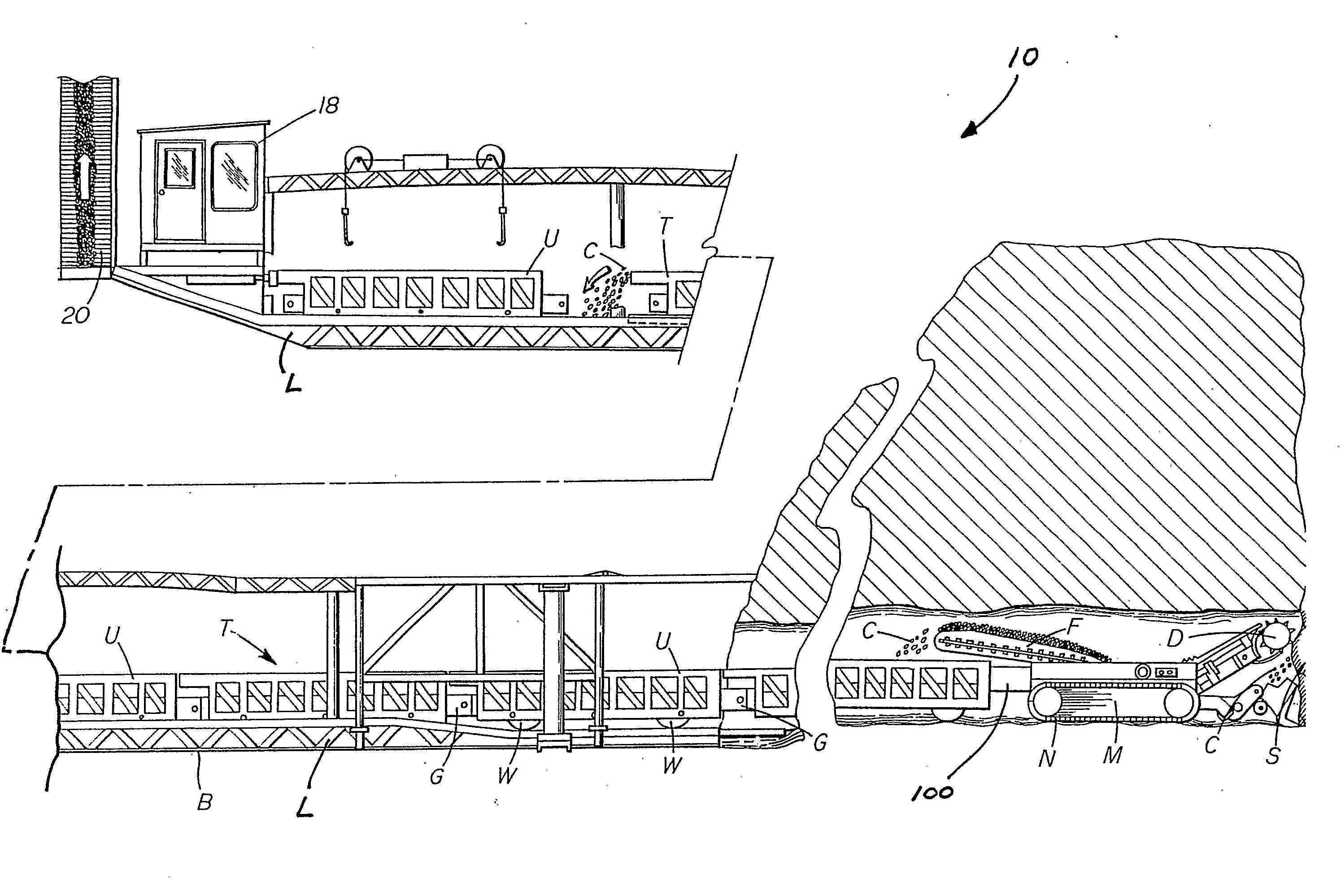
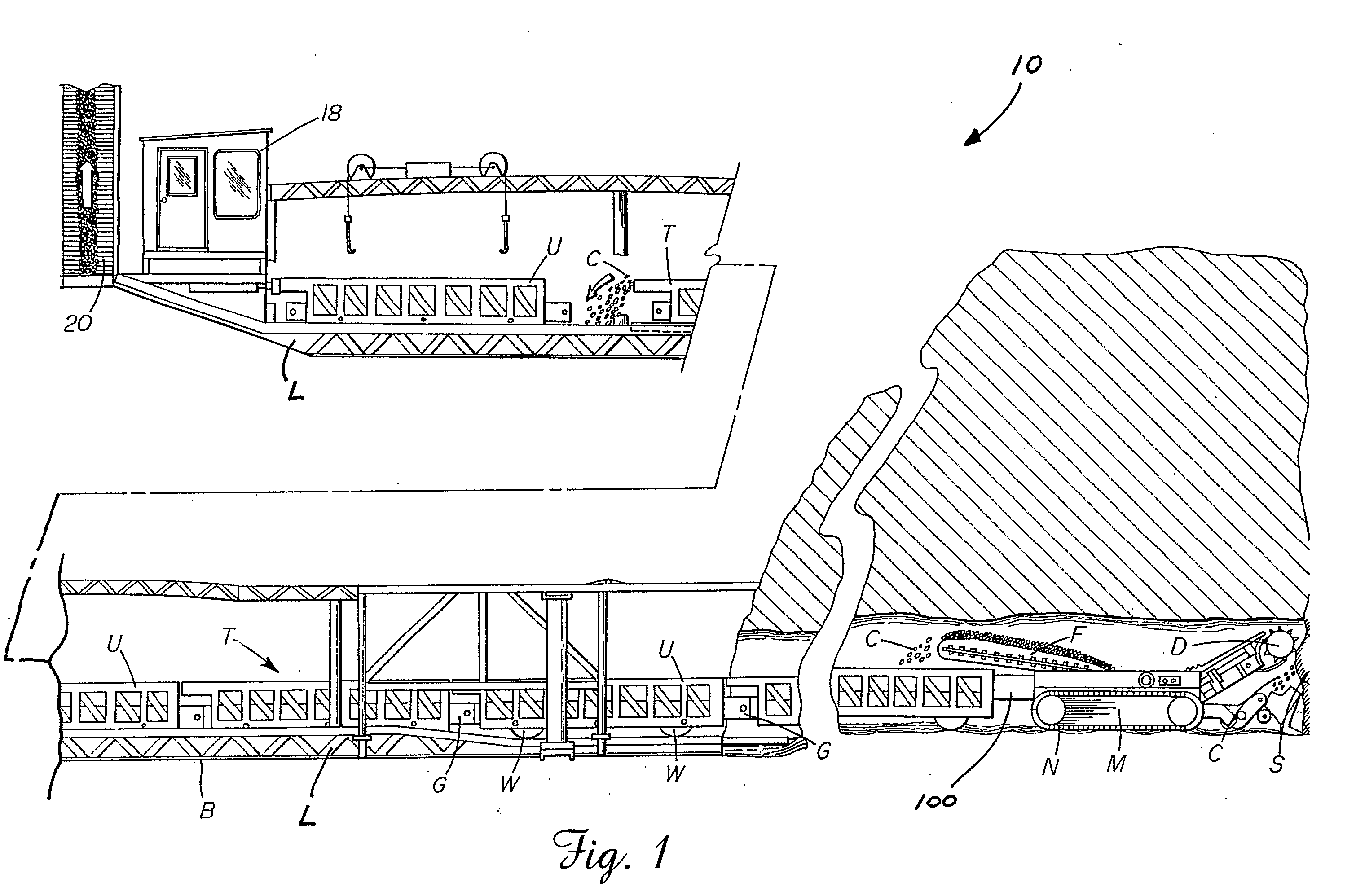
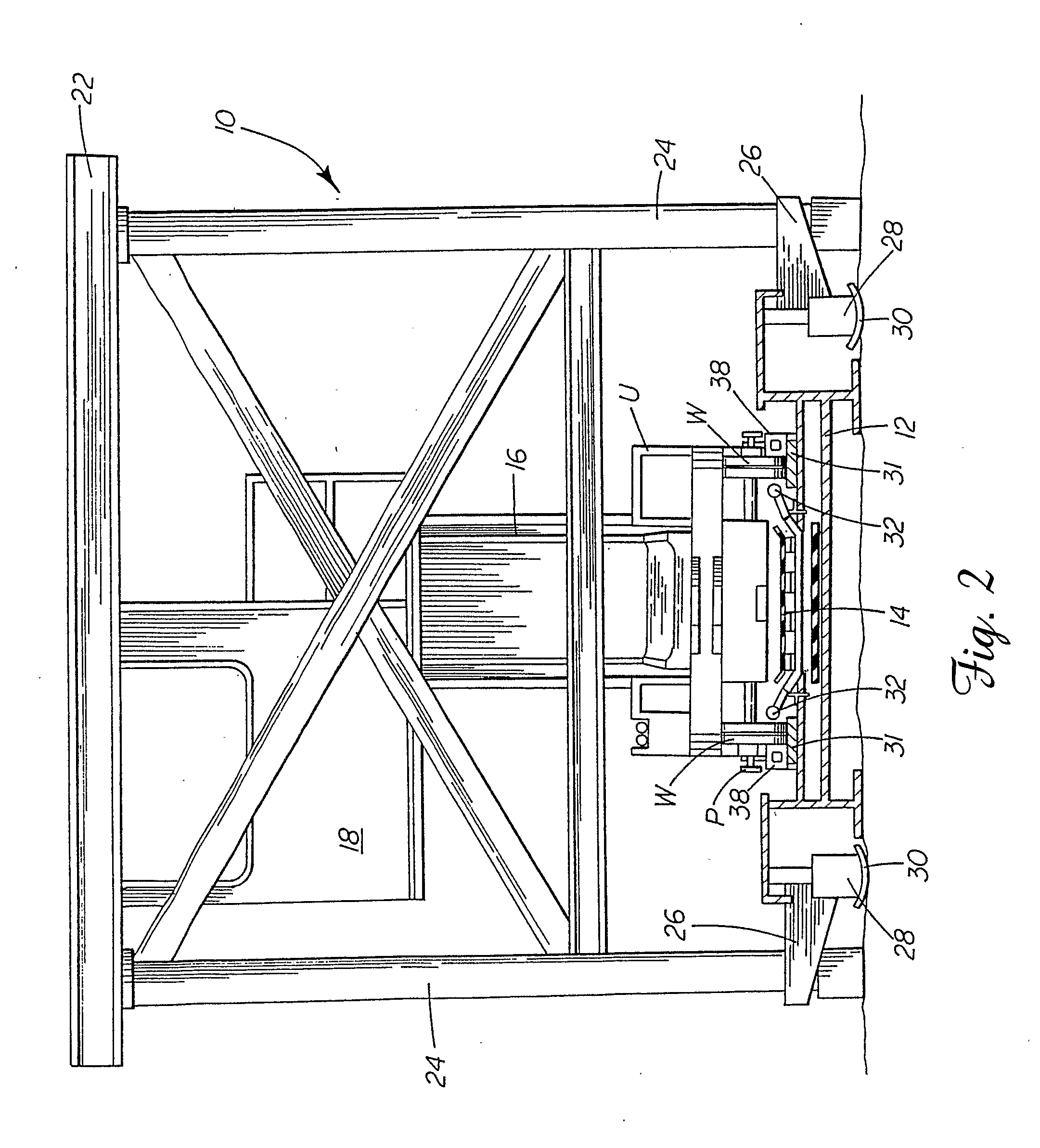
[0046] Reference is now made to FIGS. 1, 2, 3a and 3b schematically showing the mining apparatus 10 of the present invention. The mining apparatus 10 includes a launch vehicle L adapted for utilization with a continuous mining system including a continuous mining machine M of a type known in the art. The mining machine M includes a rotating cutter head drum D supporting a series of cutting bits on helical flights (not shown). The cutter head drum D is rotatably mounted on a vertically moveable boom that is pivotally mounted on the main frame member of the mining machine M. As also shown, the mining machine is supported for movement along the floor of the mine by a pair of crawler assemblies N.

[0047] In operation, the mining machine M is preferably advanced into the seam face S with the boom raised and the cutter head drum D rotating. As the cutting begins at the top level or roof line of the seam, the mining machine M is advanced further forward and the boom is gradually lowered. A...


PUM


Abstract

A mining apparatus includes a miner, a conveyor unit and a steering unit connecting the miner and conveyor unit. The apparatus also includes a heading sensor and a controller responsive to the heading sensor. A first actuator is carried on the miner, the control unit or the steering unit. The first actuator is positioned to a first side of a midline of the miner. Further a second actuator is carried on one of the miner, the conveyor unit and the steering unit. The second actuator is positioned to a second opposite side of the midline of the miner. The first and second actuators are utilized to adjust a connection angle between the miner and the conveyor unit either side of parallel in order to maintain the miner on the desired directional heading.

Description

TECHNICAL FIELD [0001] The present invention relates generally to the art of mining and, more particularly to a navigation system for a highwall miner and a highwall miner incorporating such a system. BACKGROUND OF THE INVENTION [0002] Coal, formed from decomposed and compressed vegetable matter, is typically found in substantially horizontal seams extending between sedimentary rock strata such as limestone, sandstone or shale. Surface and underground mining are the primary techniques used to recover this coal. [0003] Surface or strip mining involves the removal of material, known as overburden, overlying a coal seam so as to expose the coal for recovery. In recent years, surface mining has gained prominence over underground mining in the United States. This is due to many factors including: [0004] (a) the increased material moving capacity of surface or strip mining equipment; [0005] (b) lower costs for surface mining than underground mining; [0006] (c) the better safety record of ...

Claims


Application Information

Patent Timeline
Patent Type & Authority Applications(United States)
IPC IPC(8): E21C35/08E21C35/00E21C41/16E21C27/24
CPCE21C27/24
Inventor BAIRD, JOHN A. JR.CARR, IAN T.
Owner EAGLE HIGHWALL MINING SYST LLC
Why Eureka
Try Eureka