Method of driving fan motor

a fan motor and motor technology, applied in the direction of motor/generator/converter stopper, electronic commutator, dynamo-electric converter control, etc., can solve the problems of high switching loss in semiconductor elements such as mosfets, and achieve linear and continuous reduction of carrier frequency, reduce switching loss in semiconductor elements, and suppress driving noise

Inactive Publication Date: 2007-09-20
DENSO CORP
View PDF4 Cites 27 Cited by
  • Summary
  • Abstract
  • Description
  • Claims
  • Application Information

AI Technical Summary

Benefits of technology

[0011]The carrier frequency may be stepwise decreased to a lower frequency when the fan motor speed reaches the marginal speed. Alternatively, the carrier frequency may be linearly and continuously decreased. Preferably, the duty ratio corresponding to the marginal speed is set when a load of the fan motor deviates to the highest level. In this manner, the driving noises are surely suppressed. The low carrier frequency, with which the fan motor is driven when the motor speed reaches the marginal speed, is set to such a frequency that secures a sufficient number of switching times at a maximum speed of the fan motor.
[0012]According to the present invention, the driving noises of the fan motor are suppressed in a low speed region while reducing switching losses in the semiconductor elements in a high speed region. Other objects and features of the present invention will become more readily apparent from a better understanding of the preferred embodiments described below with reference to the following drawings.

Problems solved by technology

In the PWM control, switching losses in semiconductor elements such as MOSFETs become high when the carrier frequency is high, while driving noises of the fan motor become high in a low speed region when the carrier frequency is low.

Method used


Image

  • Method of driving fan motor
  • Method of driving fan motor
  • Method of driving fan motor

Examples


first embodiment

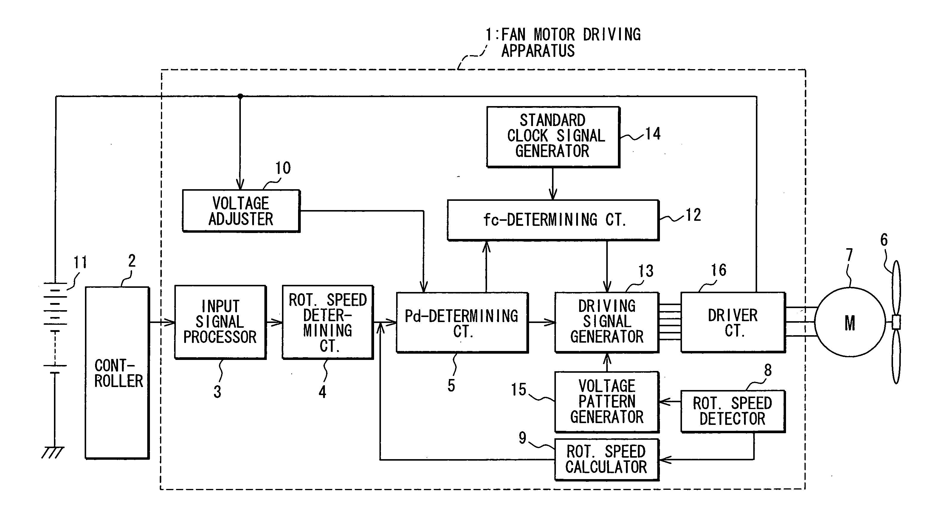
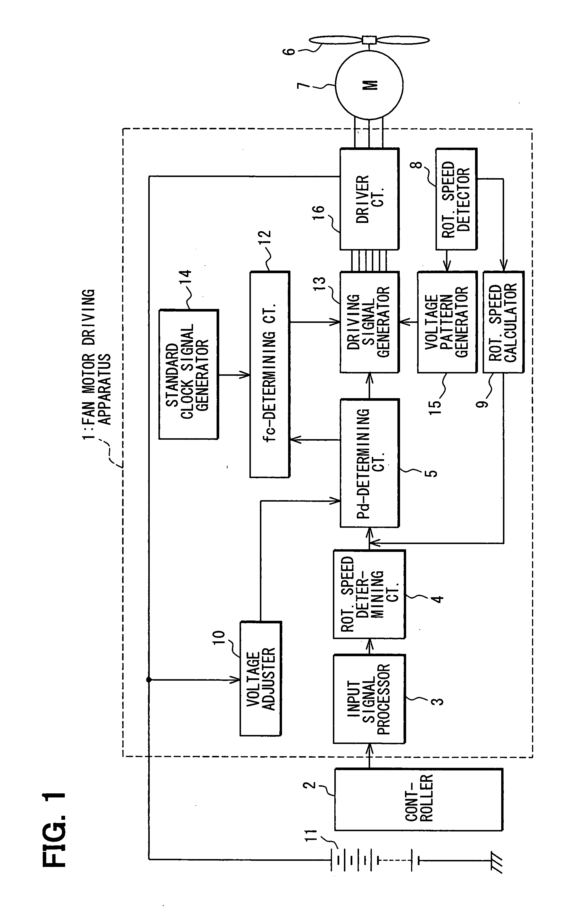
[0026]the present invention will be described with reference to FIGS. 1-8. First, referring to FIG. 1, an entire structure of a fan motor driving apparatus will be described. The driving apparatus 1 is powered by a battery 11, and supplies power to a three-phase brushless DC motor 7 that drives a fan 6. A controller 2 such as an electronic control unit (ECU) feeds a speed command (a command as to rotational speed of the motor 7) to an input signal processor 3 in the driving apparatus 1 as a PWM (Pulse Width Modulation) signal. The input signal processor 3 converts a duty ratio Rd included in the PWM signal into a duty ratio voltage Vd that represents the duty ratio Rd. The duty ratio voltage Vd is fed to a rotational speed determining circuit 4. The controller 2 outputs the speed command based on a signal, such as a water temperature in a radiator fed from a temperature sensor.

[0027]The rotational speed determining circuit 4 determines a rotational speed signal based on the duty rat...

second embodiment

[0037]the present invention is shown in FIGS. 9 and 11. In the second embodiment, the carrier frequency is stepwise reduced to fmin after the rotational speed of the motor 7 has reached the marginal speed Nm (corresponding to the marginal output duty Pdm). FIG. 9 shows a case where the carrier frequency fc is reduced to fmin in three steps. The stepwise reduction of the carrier frequency is realized, for example, in a circuit shown in FIG. 11 (though the carrier frequency is reduced in two steps in this example). In the circuit shown in FIG. 11, the carrier frequency is switched by changing a time constant of CR in a triangle wave generator 31 according to the output duty Pd. Other structures and functions are the same as those in the first embodiment.

[0038]A third embodiment of the present invention is shown in FIGS. 10 and 12. In the third embodiment, the carrier frequency is linearly and continuously reduced to the minimum carrier frequency fmin after the rotational speed N of th...


PUM


Abstract

A fan motor is driven under a pulse width modulation (PWM) control. PWM signals to be supplied to a circuit for driving the fan motor are formed from carrier waves having a specified frequency and a duty ratio of the PWM control. Rotational speed of the fan motor is increased by increasing the duty ratio. In a low speed region, the fan motor is driven with a high carrier frequency to suppress driving noises of the fan motor, while it is driven with a low carrier frequency in a high speed region to reduce switching losses in semiconductor elements. The carrier frequency may be continuously decreased when the fan motor speed reaches the high speed region, or it may be stepwise decreased. The low carrier frequency used in the high speed region is set to such a frequency that guarantees a sufficient number of switching times at a maximum speed of the fan motor.

Description

CROSS-REFERENCE TO RELATED APPLICATION[0001]This application is based upon and claims benefit of priority of Japanese Patent Application No. 2006-69176 filed on Mar. 14, 2006, the content of which is incorporated herein by reference.BACKGROUND OF THE INVENTION[0002]1. Field of the Invention[0003]The present invention relates to a method of driving a fan motor.[0004]2. Description of Related Art[0005]In a PWM (Pulse Width Modulation) control for controlling operation of a fan motor for driving a fan, a carrier frequency used in the PWM control is often set to a frequency in a neighborhood of 20 kHz that is a little beyond an audible limit of human ears in order to reduce driving noises. However, a switching loss in semiconductor elements used in the PWM control device increases according to increase in the carrier frequency. Accordingly, it is necessary to use large size semiconductors or to use a large heat dissipation member.[0006]On the other hand, JP-A-2002-142494 proposes to use...

Claims


Application Information

Patent Timeline
Patent Type & Authority Applications(United States)
IPC IPC(8): H02P3/18H02P6/08H02P6/06H02P6/12H02P6/17H02P7/29
CPCH02P6/181H02P6/08
Inventor KANAMORI, ATSUSHI
Owner DENSO CORP
Why Eureka
Try Eureka