Ink jet printing method and ink jet printing apparatus

a printing apparatus and ink jet technology, applied in printing, inking apparatus, other printing apparatus, etc., can solve the problems of fluctuation deterioration of image quality, deterioration of ink droplet landing accuracy, etc., to mitigate the decrease of the landing accuracy of ink droplets, the effect of eddy flow

Inactive Publication Date: 2007-09-20
CANON KK
View PDF1 Cites 40 Cited by
  • Summary
  • Abstract
  • Description
  • Claims
  • Application Information

AI Technical Summary

Benefits of technology

[0014] It is an objective of the present invention to provide an ink jet printing apparatus printing apparatus and an ink jet printing method by which, even when a print head in which ink ejecting sections are arr

Problems solved by technology

However, in the case of the ink jet printing apparatus printing apparatus as described above that uses a long print head having a high density, a problem as described below may be caused.
This causes a problem that positions to which ink droplets land on the print medium are fluctuated.
Furthermore, it has been known that the eddy flow between the print head and the print medium has a significant influence on how the ink droplets are ejected, which is also one of the causes of the deterioration of an ink landing accuracy.
Another problem is that the fluctuation of the ink landing positions as described above causes the image to have a stripe-like or spiral-like uneven density, remarkably

Method used


Image

  • Ink jet printing method and ink jet printing apparatus
  • Ink jet printing method and ink jet printing apparatus
  • Ink jet printing method and ink jet printing apparatus

Examples


embodiment

[0150] Next, the present invention will be described in more detail by the examples as shown below.

example 1

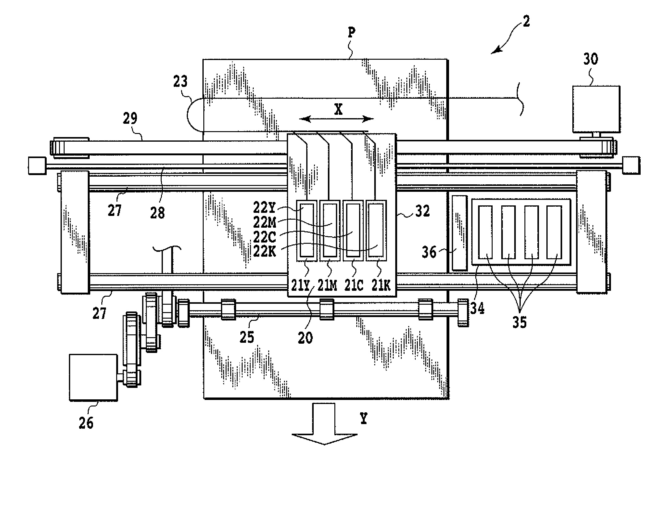
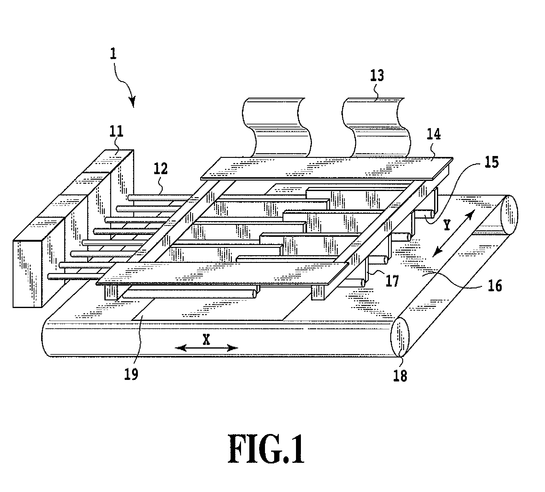
[0151] In the full-line-type ink jet printing apparatus printing apparatus shown in FIG. 1, the ink jet print head shown in FIG. 2 was used to perform a printing operation. In this operation, ink ejected from the print head was commercially-available black ink (BCI6) for BJF900 (made by Canon Inc.). Each ink droplet was set to be ejected in an amount of 2.5±0.5 pl.

[0152] With regards to a print medium, an ink jet-exclusive photo gloss paper (pro-photo paper, PR101 made by Canon Inc.) was prepared.

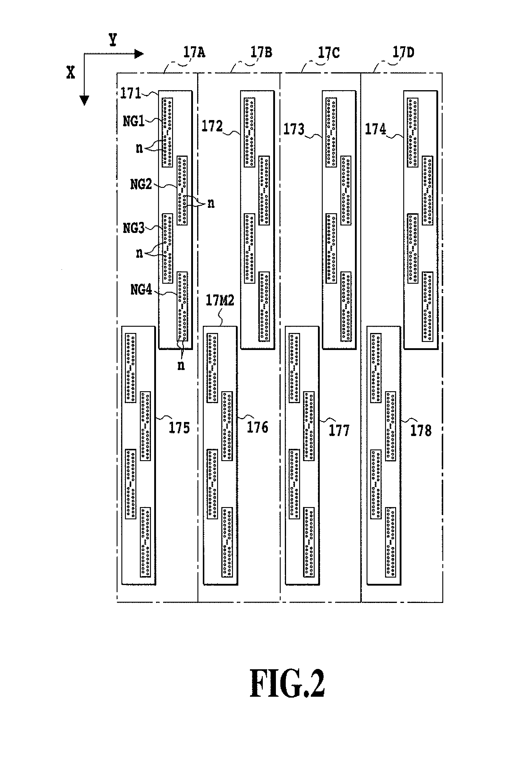
[0153]FIG. 17 schematically shows the nozzle arrays of the print head and the mask pattern M used in this example. Although the print head shown in FIG. 17 actually has the structure shown in FIG. 2, the print head in FIG. 17 is shown so that the nozzles arranged in a staggered manner shown in FIG. 2 are considered as one row for convenience.

[0154] The upstream side first nozzle array 17A consisting of the nozzle arrays 171 and 175 of FIG. 2 (intermediate nozzle array) prints to-be-print...

example 2

[0160] The same ink jet printing apparatus printing apparatus as that of Example 1 was used to perform a divided printing by the high printing ratio region and the low printing ratio region as shown in FIG. 17. In this case, the width of the high printing ratio region was increased so that a nozzle array having a density of 1200 dpi corresponds to 16 nozzles (0.32 m). The printing as described above did not cause uneven density presumably caused by an influence by eddy flow, providing an image having a high quality.


PUM


Abstract

The present invention allows a high-speed printing by a print head in which nozzles are arranged with a high density to reduce eddy flow caused between the print head and a print medium, providing an image with a high quality. Thus, the present invention allows the same printing region of the print medium to be sequentially printed by the respective nozzle arrays provided in the print head in accordance with image data thinned-out by the mask pattern M, thereby completing the image by multi-pass. Then, a plurality of pieces of image printed to be printed to the same printing region at which the nozzle arrays pass in one pass are alternately thinned-out by different high and low thinning-out ratios in the direction in which the nozzles are arranged.

Description

BACKGROUND OF THE INVENTION [0001] 1. Field of the Invention [0002] The present invention relates to an ink jet printing method and an ink jet printing apparatus printing apparatus which print an image on a print medium by using an ink jet print head having a nozzle array in which nozzles for ejecting ink are arranged with a high density. [0003] 2. Description of the Related Art [0004] With the diffusion of information processing devices and communication devices (e.g., computer, word processor), output devices for outputting digital image according to digital image information processed by the information processing devices have been increasingly required. One of these output devices is an ink jet printing apparatus printing apparatus that ejects ink droplets to form dots on a print medium to form an image. This ink jet printing apparatus printing apparatus has been widely used. This ink jet printing apparatus printing apparatus uses a print head that is designed, in order to impro...

Claims


Application Information

Patent Timeline
IPC IPC(8): B41J2/15
CPCB41J2/155B41J2202/21B41J2/5058
Inventor SHIBATA, TSUYOSHINOGUCHI, ERIYAMAGUCHI, HIROMITSU
Owner CANON KK
Why Eureka
Try Eureka