Connector

a technology of connecting rods and connecting rods, which is applied in the direction of suction devices, medical devices, other medical devices, etc., can solve the problems of negative pressure in the channel space, undesirable backflow, and risk of liquid in the channel connected to the channel space flowing backward, so as to achieve constant pressure in the accommodating chamber

Inactive Publication Date: 2007-09-20
TYCO HEALTHCARE GRP LP
View PDF45 Cites 62 Cited by
  • Summary
  • Abstract
  • Description
  • Claims
  • Application Information

AI Technical Summary

Benefits of technology

[0012]It is sufficient if the aforementioned accommodating chamber accommodates the moving part to affect channel space volume change within the moving part. Therefore, it need not accommodate a part that is deformed and moves within the external form of the original valve member. The aforementioned accommodating chamber could also be formed integrally with the channel formation part, or it could be formed separately. When formed integrally, a constitution in which a channel space and an accommodating space are formed delineated within one housing is better.
[0013]The aforementioned accommodating chamber may have a window part that connects to the outside. When the liquid supply means is attached to or pulled out of the liquid supply means connection opening, the moving member advances or retreats in the accommodating chamber and the volume of the space in the accommodating chamber changes. In this case, by providing a window part in the accommodating chamber, the pressure in the accommodating chamber may be kept constant even if the volume of the space in the accommodating chamber changes. Thus, difficulty in accommodating the moving part in the accommodating chamber or difficulty in withdrawing the moving part from the accommodating chamber can be prevented.
[0014]The aforementioned valve member is such that a slit is formed in the side facing the channel space. In addition, the aforementioned moving part has a first moving part and a second moving part formed by expanding to the two sides of the aforementioned slit when the aforementioned liquid supply means is connected to the aforementioned liquid supply means connection opening, and the aforementioned accommodating chamber has a first accommodating chamber that accommodates the aforementioned first moving part and a second accommodating chamber that accommodates the aforementioned second moving part. With a constitution such as this, the first moving part and the second moving part can easily be accommodated in the first accommodating chamber and the second accommodating chamber by the valve body splitting left and right relative to the slit. In this case, it is even better if the aforementioned slit penetrates from the outside to the aforementioned channel space. By the slit penetrating from the outside to the channel space, the liquid supply channel can be joined to the channel space through the slit when a liquid supply means is connected to the liquid supply means connection opening.
[0015]The aforementioned connector also has an auxiliary valve member that joins or disconnects the valve placement space at which the aforementioned valve member is placed and the aforementioned channel space. The auxiliary valve member closes prior to the aforementioned valve member and disconnects the aforementioned channel space and the aforementioned valve placement space when the aforementioned liquid supply means is pulled from the aforementioned liquid supply means connection opening. Since the channel space and the valve placement space are disconnected by the closing of the auxiliary valve member, a change in volume accompanying the closing of the valve member subsequently is not transmitted to the channel space. Thus, even a minute change in volume accompanying closing of the valve member can be prevented from being transmitted to the channel space, and backflow in the liquid distribution channel joined to the channel space can be prevented even more completely.

Problems solved by technology

In this case, the pressure in the channel space becomes negative pressure with the increase in volume of the channel space, and there is the risk of the liquid in the channel connected to the channel space flowing backward.
Such backflow is undesirable.

Method used


Image

  • Connector
  • Connector
  • Connector

Examples


Embodiment Construction

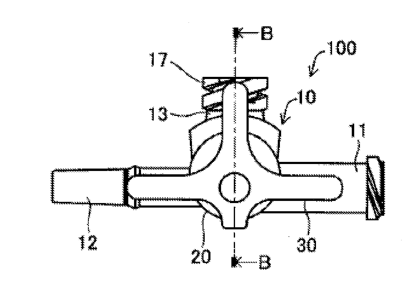
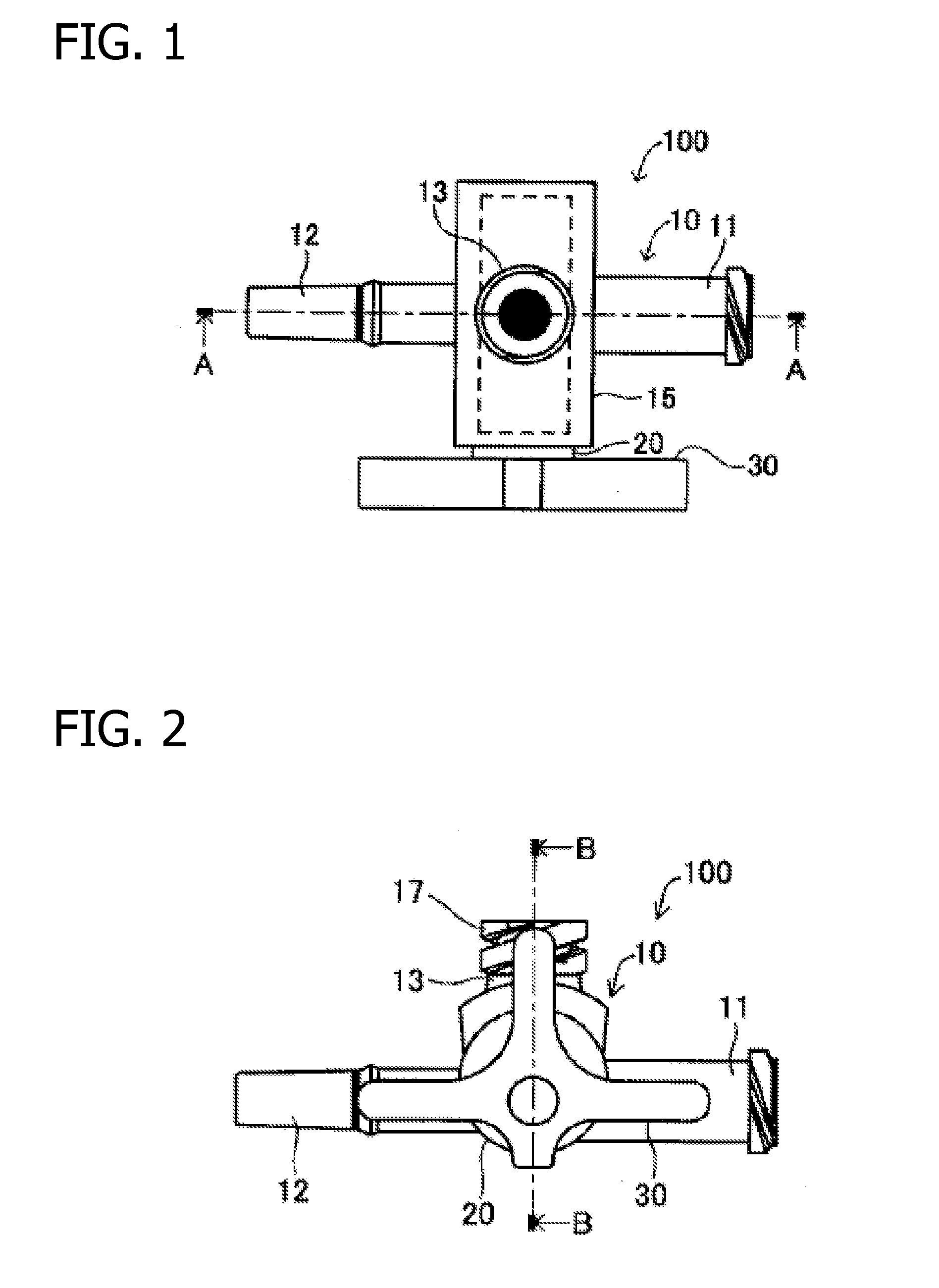
[0036]Below, a connector pertaining to the present invention will be explained in detail using figures. As the first embodiment, an example in which a connector pertaining to the present invention is used as a three-way stopcock will be explained with figures. FIG. 1 is a plan view of a three-way stopcock pertaining to the first embodiment of the present invention, FIG. 2 is a front view, and FIG. 3 is a side view with FIG. 2 as the front view. As can be seen from these figures, three-way stopcock (100) has a housing (10) that forms its contours, a stopper body (20) mounted in housing (10), and a grip part (30) formed integrally with stopper body (20).

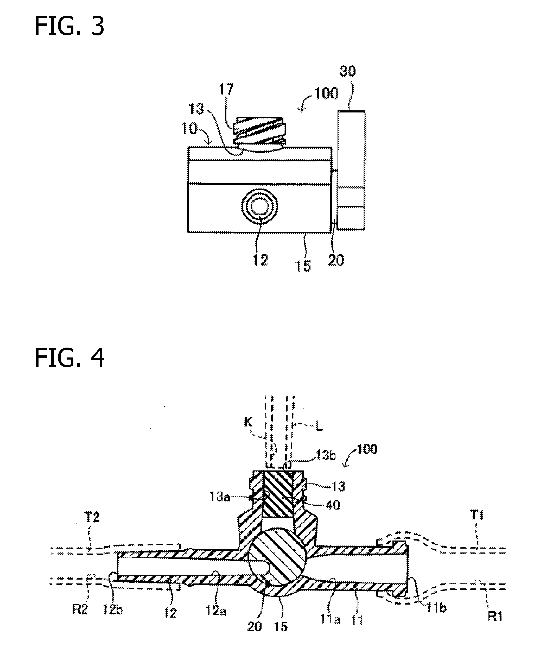
[0037]Housing (10) has a tubular part (15) and a first branch tube (11), a second branch tube (12) and a third branch tube (13), which are three branch tubes attached to tubular part (15). A round columnar space is formed inside tubular part (15). FIG. 4 is a cross section along A-A in FIG. 1. As can be seen from FIG. 4, a branch chann...


PUM


Abstract

The present invention is directed to a connector with which negative pressure in the channel space in the connector can be prevented during luer removal, in a closed-system connector. A slit ( 49 ) is furnished in valve body ( 40 ) of three-way stopcock ( 100 ). During luer access and luer removal, first and second moving parts (M 1 and (M 2 ) to the left and right of slit ( 49 ) enter and withdraw from first and second valve body accommodating chambers ( 51 ) and ( 52 ), respectively. First and second valve body accommodating chambers ( 51 ) and ( 52 ) are formed outside of channel space (S), so the operation whereby first and second moving parts (M 1 ) and (M 2 ) enter and withdraw during luer access and luer removal does not affect the change in volume of channel space (S) and negative pressure can be prevented from occurring in channel space (S) by the aforementioned entry and withdrawal.

Description

CROSS-REFERENCE TO RELATED APPLICATIONS[0001]This application claims the benefit of Japanese Patent Application No. 2006-75615 filed Mar. 17, 2006, the entire contents of which are incorporated herein by reference.TECHNICAL FIELD[0002]The present invention relates to a connector that is connected to a liquid distribution means in which is formed a liquid distribution channel. In particular, it relates to a closed-system connector that is normally closed, and opened when necessary to supply liquid to the liquid distribution channel.PRIOR ART[0003]In the medical field, transport of fluids, e.g., infusion, blood transfusion, artificial dialysis, or blood collection is often performed. To transport various types of liquids, a tube in the form of a tube body is often used as the liquid distribution means, and a connector is connected to the tube and a plurality of liquids is mixed together or shut off. The connector is attached midway in the tube, and in addition to being used as a coinf...

Claims


Application Information

Patent Timeline
Patent Type & Authority Applications(United States)
IPC IPC(8): A61M1/00
CPCA61M39/10A61M39/223A61M39/26A61M2206/20A61M2039/1027A61M2039/263A61M2039/266A61M2039/0036
Inventor KITANI, ICHIROSAKAI, YOSUKEFUNAMURA, SHIGEAKI
Owner TYCO HEALTHCARE GRP LP
Why Eureka
Try Eureka