
Partially covered stent devices and methods of use

a stent and stent technology, applied in the field of partial stents, can solve the problems of unable to repair cerebral aneurysms, too large aneurismal openings or necks, and unable to achieve surgical repair of cerebral aneurysms, so as to prevent flow

Inactive Publication Date: 2007-09-20
NFOCUS NEUROMEDICAL
View PDF2 Cites 122 Cited by
  • Summary
  • Abstract
  • Description
  • Claims
  • Application Information

AI Technical Summary

Benefits of technology

[0007] In a first aspect of the present invention, a stent device is provided for covering an aneurysm in a blood vessel, particularly wherein the blood vessel includes at least one side-branch near the aneurysm. In some embodiments, the stent device comprises a tubular frame having a first end and a second end, and a covering between the first and second ends of the frame. The covering substantially restricts flow of blood through the frame to the aneurysm while the stent device is positioned within the blood vessel so that the covering substantially covers the aneurysm. Also, the tubular frame has a cell geometry which allows sufficient flow of blood through the cell geometry at least between the ends and the covering so as to maintain blood flow through to the at least one side-branch. The frame typically also includes at least one anchoring portion which provides radial anchoring force.
[0010] In another embodiment, the stent device comprises a tubular frame having a first end, a second end, an occlusional cell geometry and an open cell geometry. The occlusional cell geometry is configured to be positioned so as to cover the aneurysm and substantially prevent flow of blood therethrough to the aneurysm while the stent device is positioned within the blood vessel. The open cell geometry is configured to be positioned so as to maintain blood flow through to the at least one side-branch while the stent device is positioned within the blood vessel. Typically, the occlusional cell geometry has smaller cells than the open cell geometry. In some embodiments, the occlusional cell geometry comprises approximately 10-90 percent of the frame, particularly approximately 30-40 percent of the frame.

Problems solved by technology

A cerebral aneurysm is an area where a blood vessel in the brain weakens, resulting in a bulging or ballooning out of part of the vessel wall.
Surgical repair of cerebral aneurysms is not possible if they are located in unreachable parts of the brain.
In some cases, the aneurismal opening or neck is too large to retain these coils.
However, the Neuroform3 Stents are only used to hold the coils in place and cannot be used independently to treat aneurysms.

Method used


Image

  • Partially covered stent devices and methods of use
  • Partially covered stent devices and methods of use
  • Partially covered stent devices and methods of use

Examples


Embodiment Construction

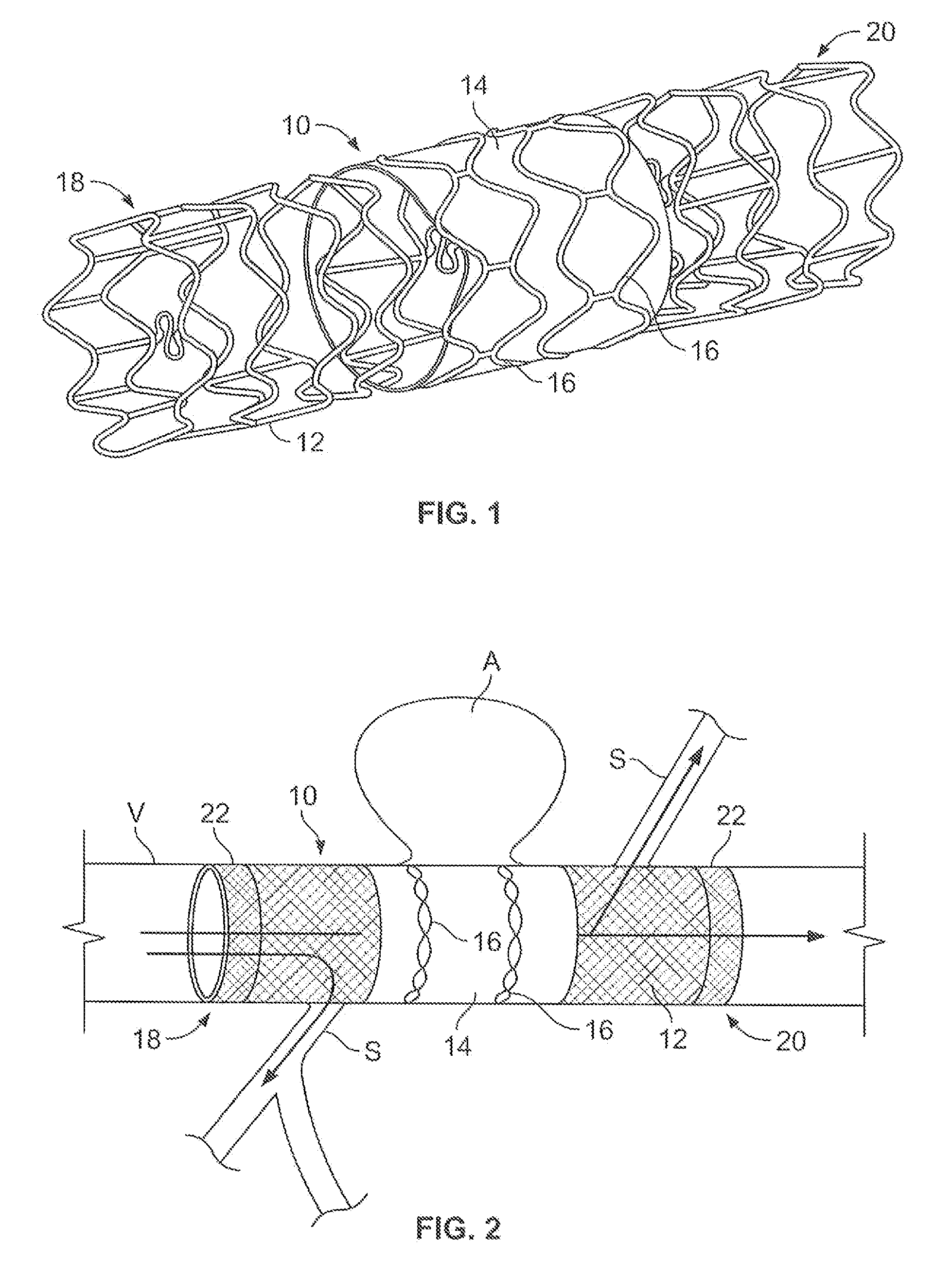
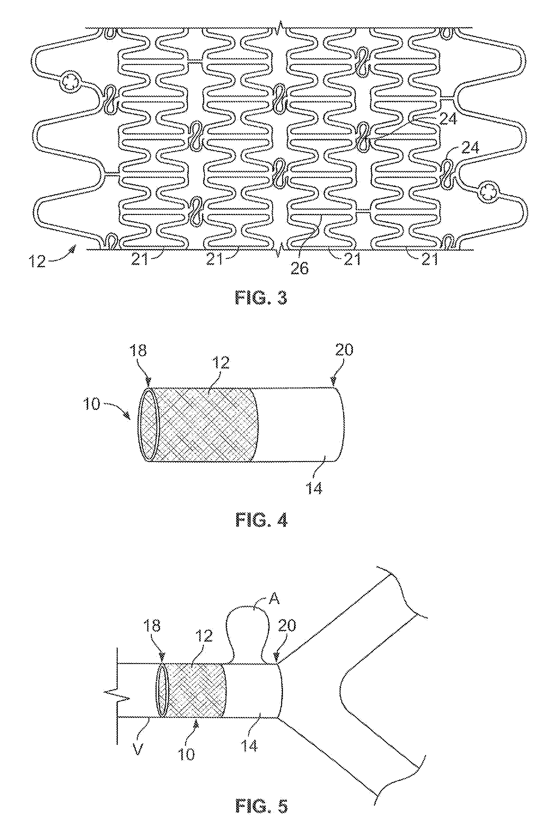
[0027]FIG. 1 illustrates an embodiment of a stent 10 of the present invention. In this embodiment, the stent 10 comprises a frame 12, a graft or covering 14, and a pair of security rings 16. The frame 12 has a tubular shape and extends from a first end 18 to a second end 20. The covering 14 is sized to cover a portion of the frame 12, typically approximately ⅓ of the length of the frame 12. In this embodiment, the covering 14 is positioned over the exterior of the frame 12 and secured in place by the security rings 16 which are positioned thereon. Additional description and embodiments are provided in later sections.

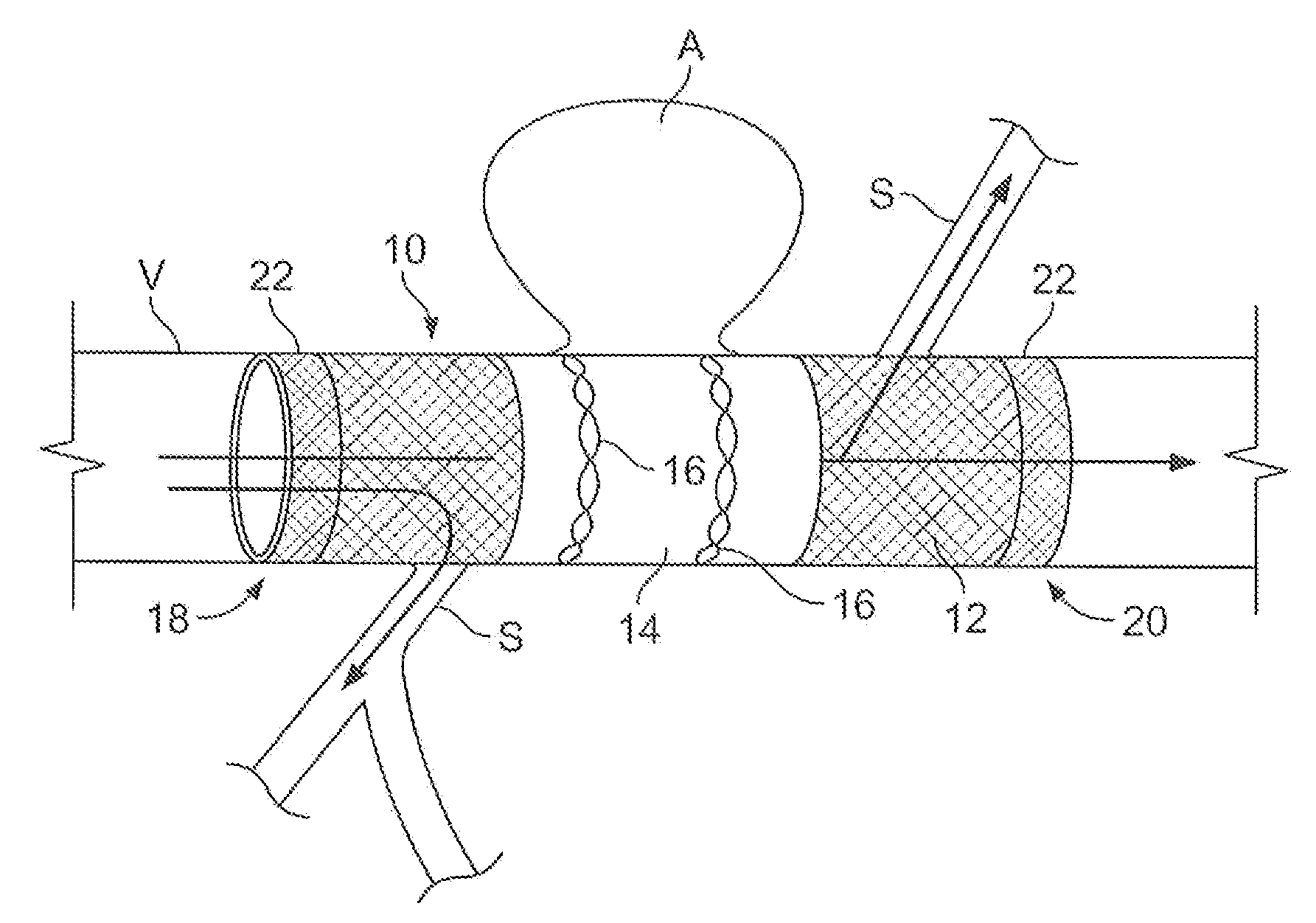
[0028]FIG. 2 illustrates the stent 10 of FIG. 1 positioned within a blood vessel V having an aneurysm A. As shown, the stent 10 is positioned so that the covering 14 covers the opening of neck of the aneurysm A, restricting blood flow into the aneurysm A. Thus, the aneurysm A is excluded from the circulation without the need for filing the aneurysm A, such as with coils...


PUM


Abstract

Devices, systems and methods are provided for treating aneurysms, particularly cerebral aneurysms. Such treatment is achieved minimally invasively without the need for conventional filling materials and methods. Such treatments may be used for aneurysms located near blood vessel side-branches and bifurcations.

Description

CROSS-REFERENCES TO RELATED APPLICATIONS [0001] This application claims priority to U.S. Provisional Patent Application No. 60 / 730,979 filed Oct. 27, 2005, incorporated herein by reference for all purposes.BACKGROUND OF THE INVENTION [0002] A cerebral aneurysm is an area where a blood vessel in the brain weakens, resulting in a bulging or ballooning out of part of the vessel wall. The disorder may result from congenital defects or from other conditions such as high blood pressure, atherosclerosis or head trauma. Every year, an estimated 30,000 people in the United States experience a ruptured cerebral aneurysm, and up to 6 percent of the population may be living with an unruptured aneurysm. Aneurysms occur in all age groups, but the incidence increases steadily for individuals age 25 and older, is most prevalent in people ages 50 to 60, and about three times more prevalent in women. The outcome for patients treated before a ruptured aneurysm is much better than for those treated aft...

Claims


Application Information

Patent Timeline
IPC IPC(8): A61F2/06A61F2/82
CPCA61F2/07A61F2/91A61F2002/075A61F2/915A61F2002/825A61F2/89A61F2002/077
Inventor DIECK, MARTIN S.DEBEER, NICHOLAS C.
Owner NFOCUS NEUROMEDICAL
Learn More