

Deterioration detecting apparatus for catalyst
- Summary
- Abstract
- Description
- Claims
- Application Information
AI Technical Summary
Benefits of technology
Problems solved by technology
Method used
Image

Examples
Embodiment Construction
[0026]Preferred embodiments of the present invention will now be described with reference to the drawings.
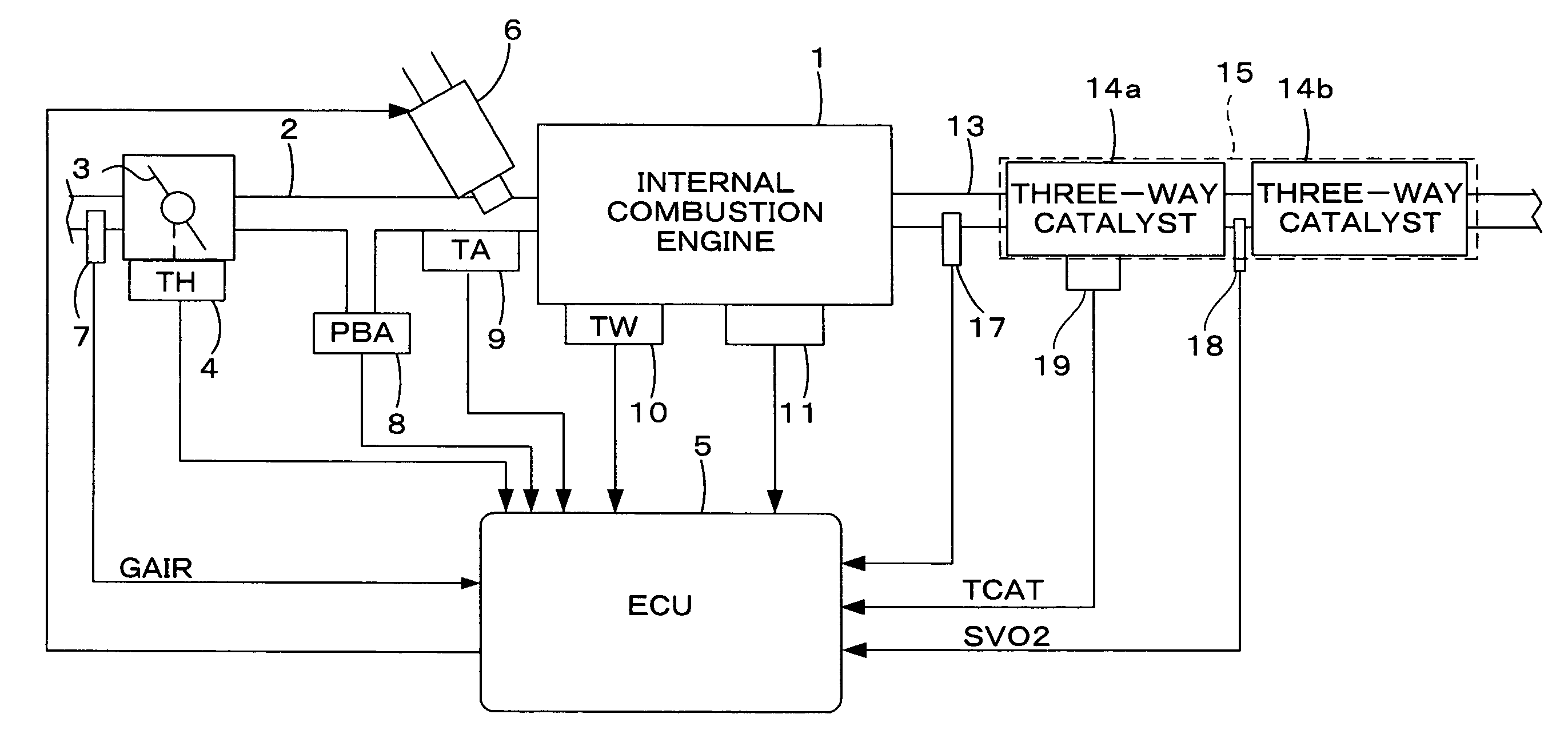
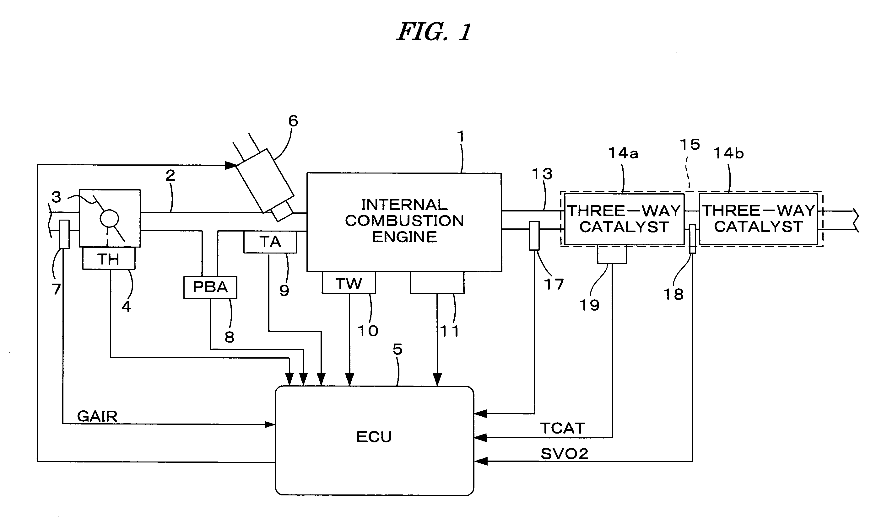
[0027]FIG. 1 is a schematic diagram showing a general configuration of an internal combustion engine (hereinafter referred to as “engine”) and a control system therefor, including a deterioration detecting apparatus for a catalyst according to one embodiment of the present invention. The engine is, for example, a four-cylinder engine 1 having an intake pipe 2 provided with a throttle valve 3. A throttle valve opening (TH) sensor 4 is connected to the throttle valve 3, so as to output an electrical signal according to the amount of opening of the throttle valve 3 and to supply the electrical signal to an electronic control unit 5 (hereinafter referred to as “ECU”).
[0028]Fuel injection valves 6 are inserted into the intake pipe 2 at locations intermediate between the cylinder block of the engine 1 and the throttle valve 3 and slightly upstream of the respective intake valves (not ...
PUM
 Abstract
Description
Claims
Application Information