
Rotary Valve for a Jack Hammer

Inactive Publication Date: 2007-09-27
SCHLUMBERGER TECH CORP
View PDF99 Cites 35 Cited by
  • Summary
  • Abstract
  • Description
  • Claims
  • Application Information

AI Technical Summary

Benefits of technology

[0006]In one aspect of the present invention a tool string comprises a jack element substantially coaxial with an axis of rotation. The jack element is housed within a bore of the tool string and has a distal end extending beyond a working face of the tool string. A rotary valve is disposed within the bore of the tool string. The rotary valve has a first disc attached to a driving mechanism and a second disc axially aligned with and contacting the first disc along a flat surface. As the discs rotate relative to one another at least one port formed in the first disc aligns with another port in the second disc. Fluid passed through the ports is adapted to displace an element in mechanical communication with the jack element. In a downhole environment, a the fluid displaces the element, the jack element oscillates, thereby furthering the penetration into a formation.

Problems solved by technology

However, only a portion of the drilling fluid may pass through the fluid ports.

Method used


Image

  • Rotary Valve for a Jack Hammer
  • Rotary Valve for a Jack Hammer
  • Rotary Valve for a Jack Hammer

Examples


Embodiment Construction

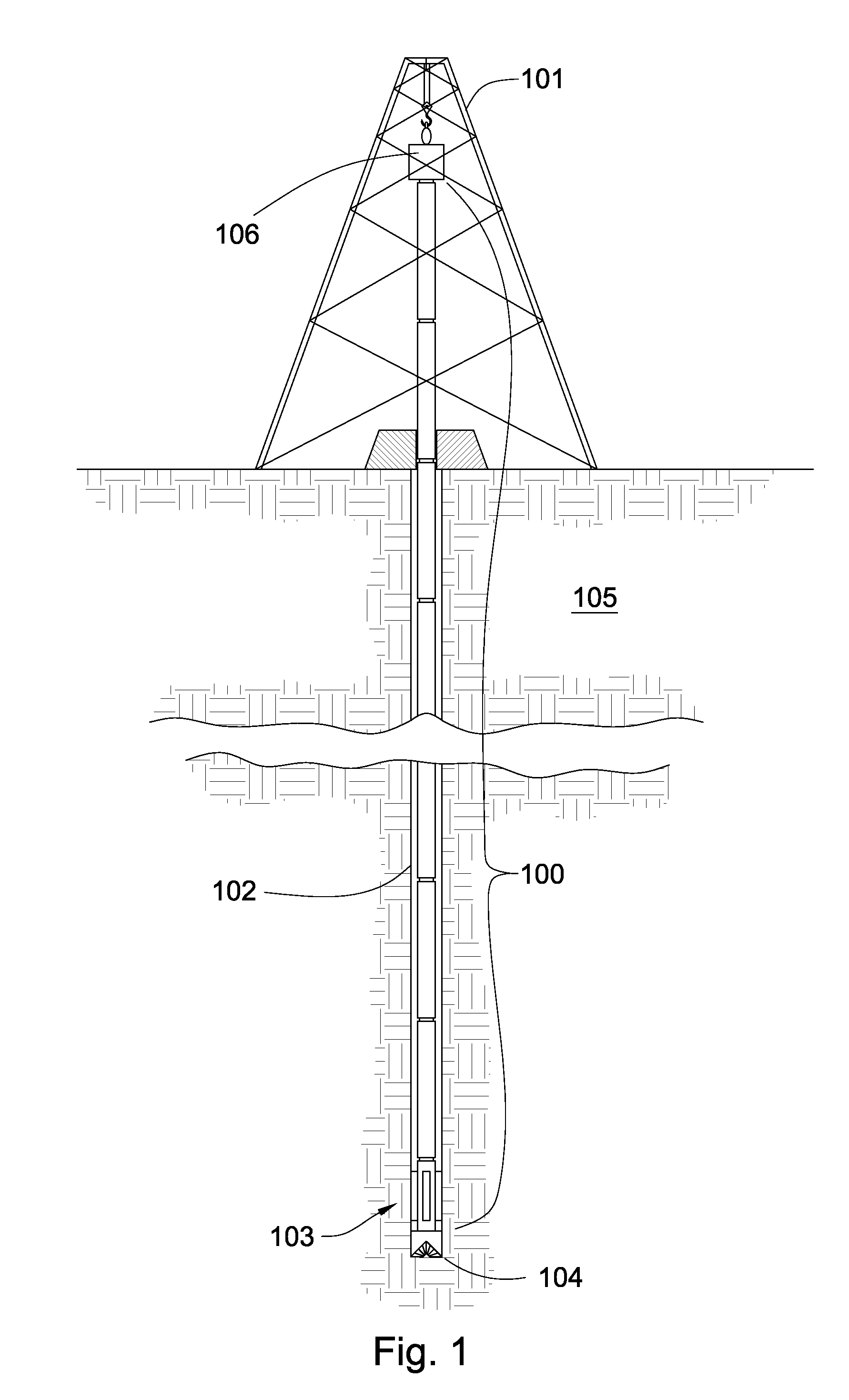
[0019]FIG. 1 is a perspective diagram of an embodiment of a tool string 100 suspended by a derrick 101 in a bore hole 102. A bottom-hole assembly 103 is located at the bottom of the bore hole 102 and comprises a drill bit 104. As the drill bit 104 rotates downhole the tool string 100 advances farther into the earth. The drill string 100 may penetrate soft or hard subterranean formations 105. The bottom-hole assembly 103 and / or downhole components may comprise data acquisition devices which may gather data. The data may be sent to the surface via a transmission system to a data swivel 106. The data swivel 106 may send the data to the surface equipment. Further, the surface equipment may send data and / or power to downhole tools and / or the bottom hole assembly 103. U.S. Pat. No. 6,670,880 which is herein incorporated by reference for all that it contains, discloses a telemetry system that may be compatible with the present invention; however, other forms of telemetry may also be compat...


PUM


Abstract

In one aspect of the present invention a tool string comprises a jack element substantially coaxial with an axis of rotation. The jack element is housed within a bore of the tool string and has a distal end extending beyond a working face of the tool string. A rotary valve is disposed within the bore of the tool string. The rotary valve has a first disc attached to a driving mechanism and a second disc axially aligned with and contacting the first disc along a flat surface. As the discs rotate relative to one another at least one port formed in the first disc aligns with another port in the second disc. Fluid passed through the ports is adapted to displace an element in mechanical communication with the jack element.

Description

CROSS REFERENCE TO RELATED APPLICATIONS[0001]This patent application is a continuation-in-part of U.S. patent application Ser. No. 11 / 680,997 filed on Mar. 1, 2007 and entitled Bi-center Drill Bit. U.S. patent application Ser. No. 11 / 680,997 is a continuation-in-part of U.S. patent application Ser. No. 11 / 673,872 filed on Feb. 12, 2007 and entitled Jack Element in Communication with an Electric Motor and / or generator. U.S. patent application Ser. No. 11 / 673,872 is a continuation-in-part of U.S. patent application Ser. No. 11 / 611,310 filed on Dec. 15, 2006 and which is entitled System for Steering a Drill String. This patent application is also a continuation-in-part of U.S. patent application Ser. No. 11 / 278,935 filed on Apr. 6, 2006 and which is entitled Drill Bit Assembly with a Probe. U.S. patent application Ser. No. 11 / 278,935 is a continuation-in-part of U.S. patent application Ser. No. 11 / 277,294 which filed on Mar. 24, 2006 and entitled Drill Bit Assembly with a Logging Devic...

Claims


Application Information

Patent Timeline
IPC IPC(8): E21B4/00
CPCE21B4/14
Inventor HALLWAHLQUIST, DAVID
Owner SCHLUMBERGER TECH CORP
Features
  • Generate Ideas
  • Intellectual Property
  • Life Sciences
  • Materials
  • Tech Scout
  • Unparalleled Data Quality
  • Higher Quality Content
  • 60% Fewer Hallucinations
Learn More