
Spring strut tube assembly

Inactive Publication Date: 2007-09-27
MUHR UND BENNDER KG
View PDF13 Cites 8 Cited by
  • Summary
  • Abstract
  • Description
  • Claims
  • Application Information

AI Technical Summary

Benefits of technology

[0005] It is an object of the present invention to provide a sturdy spring strut tube of lightweight construction which can be produced cost-effectively. SUMMARY OF THE INVENTION
[0006] A spring strut tube assembly according to the invention includes an outer container tube, such as a tubular member. The tubular member can be produced from a flexibly rolled flat material having a wall thickness that is variable in a longitudinal direction. The tubular member can be formed into a tube in a direction transversely to the longitudinal direction, and welded in the longitudinal direction, i.e., length-wise. Thus, the outer container tube—or tubular member—is provided with a wall thickness that is variable in the longitudinal direction from one end to the other. The process technology of flexible rolling allows the cost-effective production of strips or sheets from a material whose wall thickness is greatly variable (i.e. “rolled flexibly”).
[0007] The outer container tube can be comprised of several tube sections, and accordingly can be produced from individual strip portions or sheets, which are cut into lengths, bent into tube members transversely to the direction of rolling, and then welded together along a longitudinal seam. It is also possible and easy to produce cross-sections which are non-uniform along their length. A process of producing such tubular members is described in DE 10 2004 017 343 A1 of the Applicant. More particularly, it is explained that the strip material cut into lengths is first deep-drawn transversely to the longitudinal axis. Thereafter the side edges are cut and the tubular member is bent round and closed by welding. If the side edges form a butt joint along a straight surface line of the tubular member, the welding operation can be carried out particularly advantageously and securely.

Problems solved by technology

This results in substantially constant stress conditions in the tubular member in the longitudinal direction when under loaded operation.

Method used


Image

  • Spring strut tube assembly
  • Spring strut tube assembly
  • Spring strut tube assembly

Examples


Embodiment Construction

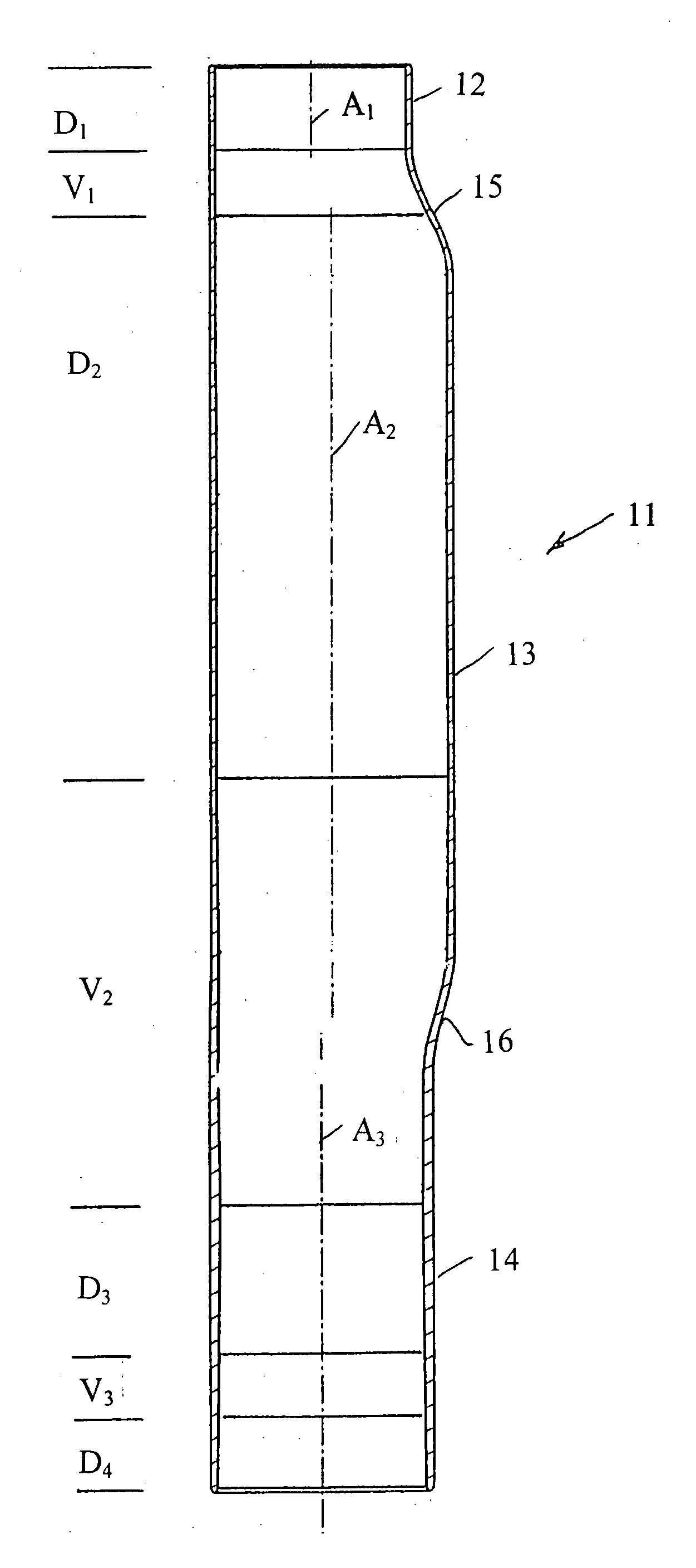
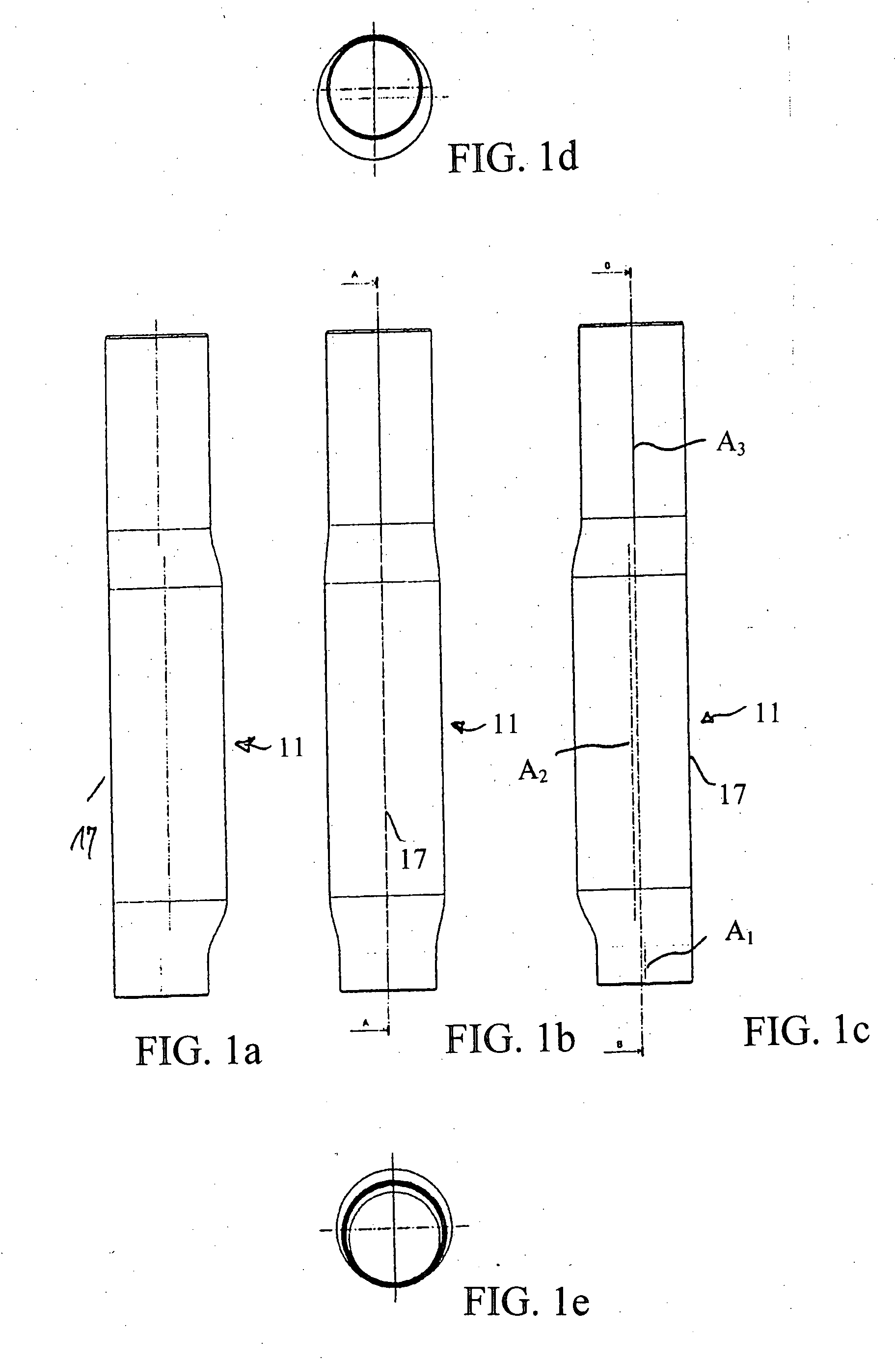
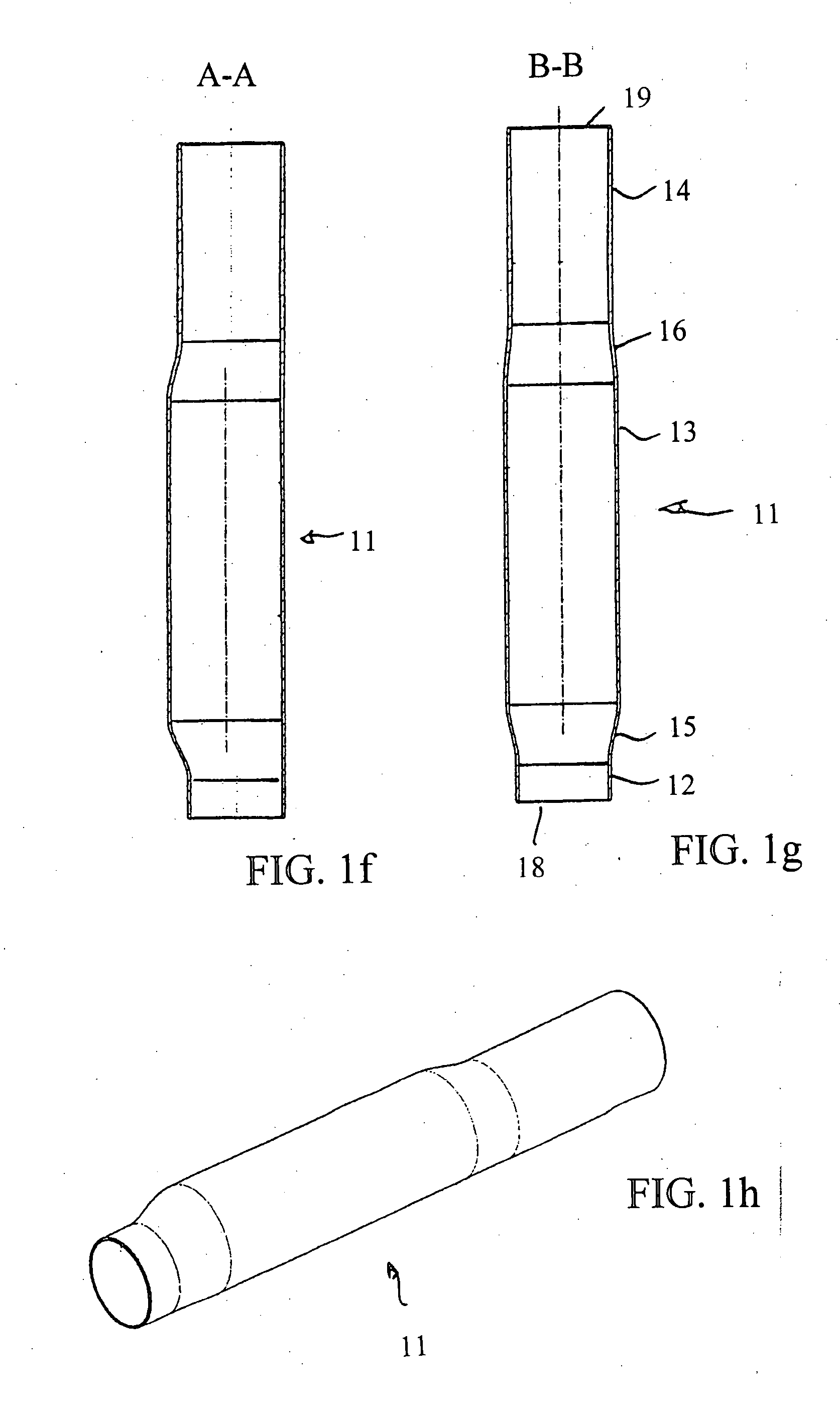
[0054]FIG. 1 shows an outer container tube, or tubular member 11, of a spring strut tube assembly according to the invention in different Figures. In the figure, the tubular member 11 has been turned by 180° from a mounted position (shown later) i.e. the tube end shown at the top, generally points downward in the mounted condition and is closed by a bottom part. The tube end shown at the bottom, generally points upward in a mounted position and remains open. An outer container tube, or tubular member 11 can be provided with three cylindrical tube portions 12, 13, 14 which are connected to one another by inclined conical transition portions 15, 16. As shown, a first cylindrical portion 12 is provided with a smaller outer diameter, a second cylindrical portion 13 is provided with a greater outer diameter and a third cylindrical portion 14 is provided with a smaller outer diameter, with the outer diameter of the tubular portion 14 slightly deviating from the outer diameter of the first...


PUM


Abstract

A spring strut tube assembly having an outer container tube, or tubular member and a spring plate. One end of the tube can be closed by a bottom part and the other end of the tube can comprise an aperture and a slid-on spring plate. The tubular member can be produced from a flexibly rolled flat material whose wall thickness is variable in the longitudinal direction. The tube is formed in a direction transverse to the longitudinal direction, and can be welded in the longitudinal direction.

Description

FIELD OF THE INVENTION [0001] The invention relates to a spring strut tube assembly, more particularly to an outer container tube for a suspension strut. The outer container tube has a tubular structure which, a first end, can be closed by a bottom part and which, at the other end, comprises an aperture. The spring strut tube assembly also includes a slid-on spring plate carried by the outer container tube, which can be connected at the other end. Suspension strut tubes of this type serve as outer tubes or, respectively, container tubes of two-tube suspension struts which are fixed by additional fixing means. For example, fixing means can be provided in the form of welded-on brackets to a wheel carrier and / or to longitudinal or transverse suspension arms of a motor vehicle and which support a helical spring on the spring plates. [0002] Such two-tube suspension struts, in addition to the outer or container tube referred to here, comprise a working cylinder which is held concentricall...

Claims


Application Information

Patent Timeline
IPC IPC(8): F16F9/00
CPCF16F9/3235
Inventor KOBELEV, VLADIMIRHAUGER, ANDREASBRECHT, JORGE DIETERSTRETZ, KLAUSSCHULER, MANFRED
Owner MUHR UND BENNDER KG
Learn More