Connector for laundry rack

Inactive Publication Date: 2007-09-27
SABOUNJIAN AZAD
View PDF13 Cites 17 Cited by
  • Summary
  • Abstract
  • Description
  • Claims
  • Application Information

AI Technical Summary

Benefits of technology

[0011] To engage the socket connector to the tab connector, the tab portion is inserted into a gate of the through-hole of the socket portion with the retention members pointed toward the through hole. As the tab portion proceeds through the through hole, retention members of the tab portion deflect inwardly due to the inner surface of the through hole. Also, the cross member may be received into the U shaped cut out. When the tab portion is fully inserted into the through hole, the retention members engage cam edges of the socket portion preventing removal of the ta

Problems solved by technology

Conventional laundry drying racks may be used to dry laundered items when the laundered items are too delicate to be placed in an electric dryer because the laundered items may shrink when exposed to excessive heat.
Unfortunately, conventional laundry drying racks, fr

Method used


Image

  • Connector for laundry rack
  • Connector for laundry rack
  • Connector for laundry rack

Examples


Embodiment Construction

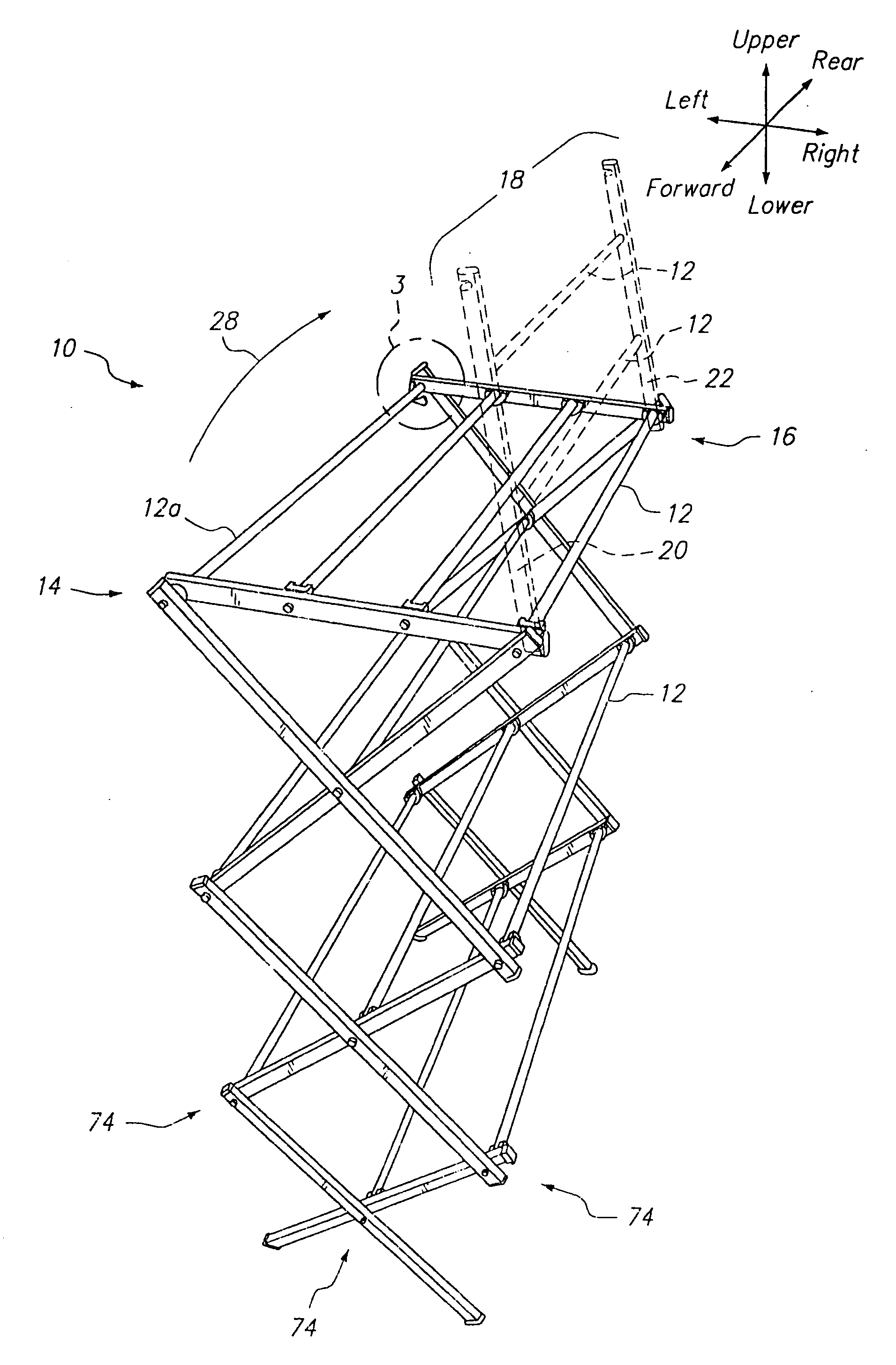
[0029] As a preliminary matter, references to upper, lower, right, left, forward and rear are for convenience and are not meant to limit the scope of the aspects of the laundry rack.

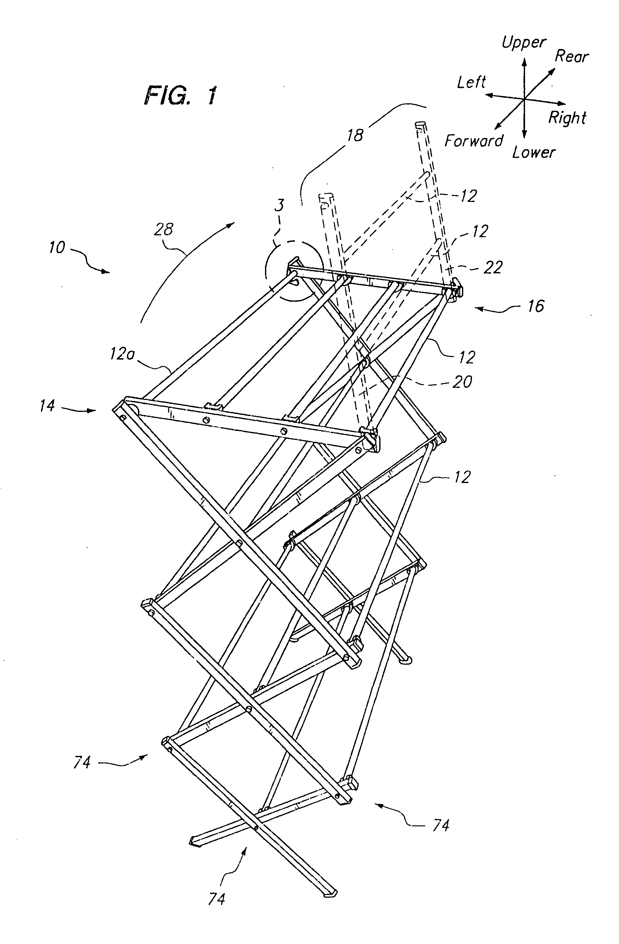
[0030] Referring now to the drawings which are for the purposes of illustration and not for the purposes of limiting the laundry rack 10 which will be described herein, FIG. 1 shows a perspective view of a laundry rack 10 which is collapsible into a folded position (See FIG. 2) and expandable to an upright position (See FIG. 1). Cross members 12 are disposed apart from each other such that laundry (e.g., shirts, pants, etc.) may be hung over the cross members 12 for air drying. After the clothes are air-dried, the user may remove the clothes and traverse the laundry rack 10 to the folded position (See FIG. 2) for compact storage. The laundry rack 10 provides a convenient mode of storage by being collapsible to the folded position so as to occupy a minimal amount of space. The folded laundry rack may the...


PUM


Abstract

A collapsible laundry rack is provided wherein a plurality of cross members for hanging clothes may be attached to first and second scissor structures via a plurality of tab connectors and socket connectors. In particular, the distal ends of the cross members may be attached to the socket connector which is selectively removable from tab connectors attached to corresponding points of the first and second scissor structures. A socket portion of the socket connector may be aligned to a tab portion of the tab connector. Release levers formed on the tab portion may be inserted into the socket until retention members of the tab portion engage cam edges of the socket portion. To remove the tabs from the socket, the release levers may be inwardly deflected to deflect the retention members inwardly to release the retention members from the cam edges. Alternatively, the tab connectors may be attached to distal ends of the cross members. Also, the socket connectors may be attached to corresponding points of the first and second scissor structures.

Description

CROSS-REFERENCE TO RELATED APPLICATIONS [0001] The application claims the benefit under 35 U.S.C. § 119(e), of application Ser. No. 60 / 782,214, filed Mar. 14, 2006, the entire contents of which are incorporated herein by reference.STATEMENT RE: FEDERALLY SPONSORED RESEARCH / DEVELOPMENT [0002] Not Applicable BACKGROUND [0003] The present invention relates generally to laundry drying racks, and more particularly to collapsible laundry drying racks. [0004] Conventional laundry drying racks may be used to dry laundered items when the laundered items are too delicate to be placed in an electric dryer because the laundered items may shrink when exposed to excessive heat. Laundry drying racks may also be used to temporarily store clothes during ironing tasks. For example, a user may place a plurality of ironed shirt on the laundry rack to prevent the ironed shirts from wrinkling as would occur if the ironed shirts were stacked upon each other. [0005] In order to minimize the price of the la...

Claims


Application Information

Patent Timeline
IPC IPC(8): A47B43/00
CPCD06F57/06
Inventor SABOUNJIAN, AZAD
Owner SABOUNJIAN AZAD
Why Eureka
Try Eureka