Image pickup apparatus

a pickup apparatus and image technology, applied in the field of image pickup apparatus, can solve the problem of extremely low detection accuracy, and achieve the effect of accurate detection

Inactive Publication Date: 2007-09-27
ITOH HIROSHI
View PDF3 Cites 9 Cited by
  • Summary
  • Abstract
  • Description
  • Claims
  • Application Information

AI Technical Summary

Benefits of technology

[0017] To eliminate the above problems in image pickup apparatus having a conventional means for eliminating dark currents or in image pickup apparatus having a means for correcting defects, it is an object of the present invention to provide an image pickup apparatus in which dark current components occurring at image pickup device can be eliminated so that fault pixels are accurately detected.
[0018] It is another object of the invention to provide an image pickup apparatus in which dark current components occurring at image pickup device can be eliminated with greatly reducing a loss in time for taking image so that fault pixels are accurately detected.

Problems solved by technology

The detection accuracy thereof becomes extremely low.

Method used


Image

  • Image pickup apparatus
  • Image pickup apparatus
  • Image pickup apparatus

Examples


first embodiment

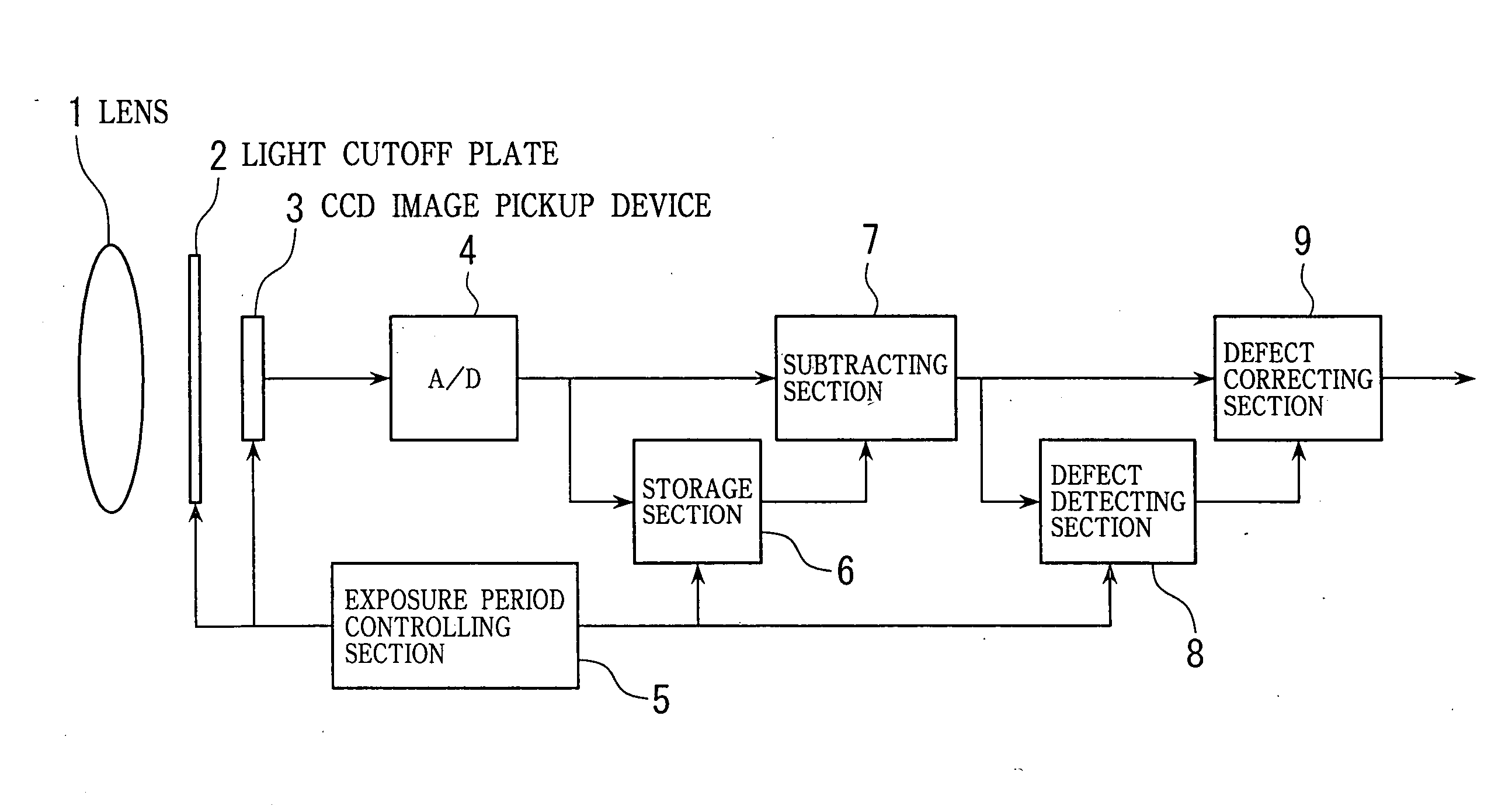
[0064] Some embodiments of the present invention will now be described. FIG. 6 is a block diagram showing the image pickup apparatus according to the present invention. The invention is not limited to black-and-white image pickup apparatus and can be applied to image pickup apparatus of any type such as color image pickup apparatus. For ease of explanation, however, one applied to an electronic camera using black-and-white CCD image pickup device will be shown in the following embodiments including the present embodiment.

[0065]FIG. 6 includes: 1, a lens for causing an incidence of object light; 2, light cutoff plate; 3, CCD image pickup device for converting the object light into electrical signals; 4, an analog-to-digital converter for converting image pickup signals outputted from CCD image pickup device 3 into digital signals; and 5, an exposure period controlling section for controlling the light cutoff plate 2, CCD image pickup device 3 and a diaphragm (not shown) to control su...

second embodiment

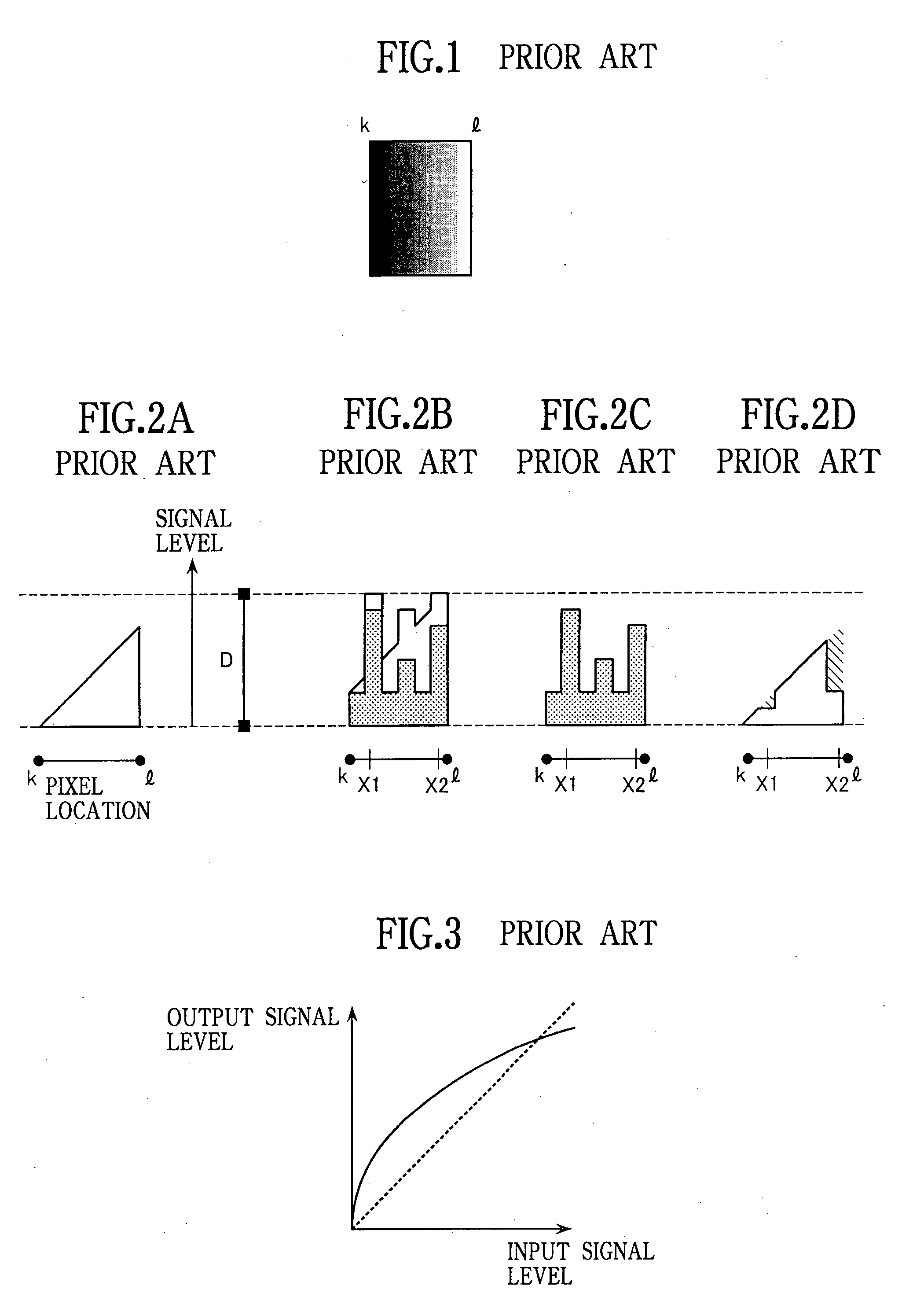
[0100] By the above processing, the signals after dark current subtraction are changed from of the waveform shown in FIG. 2D to of the waveform shown in FIG. 19. In particular, the difference with the surrounding normal pixels becomes conspicuous for the pixels of X1, X2 of which signal components have been cut down, especially with respect to X1 pixel at the lower luminance side of which the difference with the surrounding pixels after the cut-down has become smaller. It thus becomes easier to detect the lower-luminance side dark current subtraction error pixels as defects. It should be noted that main portions of this embodiment can be applied also to the second embodiment shown in FIG. 8.

[0101] An eighth embodiment will now be described. A diagrammatic representation of this embodiment is the same as the seventh embodiment shown in FIG. 18 and will be omitted. The storage section 6 serves as a main exposure image pickup signal storage section 6 and stores main exposure image pick...


PUM


Abstract

An image pickup apparatus including: CCD image pickup device for converting object light into electrical signals; a light cutoff plate; an exposure controlling section for controlling the light cutoff plate and image pickup device to control exposure period of the image pickup device; a dark signal storage section for storing dark signals obtained from the image pickup device in the condition where the incident light is cut off by the light cutoff plate; a subtracting section for subtracting dark signals stored at the storage section from the main exposure image pickup signals obtained at the image pickup device by a main exposure where the light cutoff plate is withdrawn; a defect detecting section for detecting fault pixels from the image pickup signals after the subtraction of dark current components; and a correcting section for correcting the detected fault pixels. The detection of fault pixels is performed with respect to the image pickup signals canceled of the dark current components so that the fault pixels can be accurately detected.

Description

RELATED APPLICATIONS [0001] This application is a divisional application of U.S. patent application Ser. No. 10 / 331,267 (titled “IMAGE PICKUP APPARATUS,” filed on Dec. 30, 2002, listing Hiroshi Itoh as the inventor), which claims benefit of Japanese Application No. 2002-1921 filed in Japan on Jan. 9, 2002. The contents of these applications are incorporated herein by this reference.BACKGROUND OF THE INVENTION [0002] The present invention relates to image pickup apparatus in which it is possible to eliminate dark current components occurring at image pickup device such as a solid-stateimage pickup device and to detect and correct fault pixels so that suitable image pickup signals can be obtained. [0003] In recently developed image pickup apparatus, solid-state image pickup devices typically represented by CCD are commonly used as an image pickup / input device. A solid-state image pickup device is an aggregate of several millions of very small pixels and input light is converted into a...

Claims


Application Information

Patent Timeline
Patent Type & Authority Applications(United States)
IPC IPC(8): H04N9/64H04N1/028G06T1/00H04N5/335H04N5/353H04N5/361H04N5/367H04N5/372H04N5/378
CPCH04N5/367H04N5/361H04N25/63H04N25/68
Inventor ITOH, HIROSHI
Owner ITOH HIROSHI
Why Eureka
Try Eureka